The suggested design describes a basic procedure for employing the excess solar energy from a solar panel for heating water in water tanks or swimming pools or poultry egg chambers. Generally the circuit also features just like an automatic solar battery charger, and at the same time powers domestic electrical appliances.
Solar energy is abundantly accessible around the world and it's totally free to utilize. It's exactly about positioning a solar energy collector or simply just a solar PV panel, and utilize the obtainable resource.
Within this site and in a number of other sites you may have discover a variety of economical solar battery charger circuits. In spite of this these circuits usually talk about utilizing the solar panel for getting electrical energy.
Although working, the required regulators/chargers stabilize the solar voltage such that the output voltage becomes appropriate for the attached battery which can be generally a 12V lead acid battery.
Considering that usually a solar panel is meant for producing voltages in excess of 12V, that is around 20 to 30 volts, the means of stabilization totally neglects the excess voltage which is often overlooked to ground or stopped out by means of electronic circuitry.
In the existing post we understand an easy technique of transforming additional solar energy to heat at the same time charging a battery, and running household devices securely with each other.
The circuit working might be recognized with the following details:
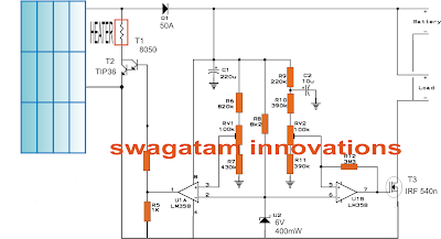
In the presented solar water heater with battery charger controller circuit diagram, let's believe at peak sunshine the attached solar panel is capable of producing around 24V.
In the diagram we are able to observe a number of opamps placed relating to the solar input and the battery charging outlet.
The opamp at the left is essentially set for enabling the stipulated charging voltage to its right hand side phases.
For a 12V battery this voltage could well be around 14.4V.
RV1 is consequently modified such that the output of the opamp turns into high in case the input voltage surpasses the 14.4V mark.
The opamp at the right is chosen as the over charge cut off stage which is accountable for checking the charging voltage of the battery, and cut it off when the upper guideline is attained.
Such things happen when the non inverting input of U1B sustains the higher threshold and shuts off the positive bias to the mosfet which often cuts off power to the associated battery.
On the other hand the load which is basically an inverter remains functioning, as now it begins deriving the power from the charged battery.
In the course, if the voltage falls even by a few voltages, U1B reverts its output to logic high and the battery as just stated starts getting charged while at the same time permitting the linked appliances to remain operative via the common panel voltage.
In the mean time as mentioned in the earlier lines, U1A detects the panel voltage and exactly like U1B when it immediately feels the panel voltage going above the 14.4 mark, it switches its output to logic high so that the associated transistors are immediately turned on.
A DC heater coil may be seen connected across the collector and positive of the transistor.
When the transistor performs, the coil is overlooked across the direct panel voltage, thereby it immediately commences obtaining hot.
The low resistance of the coil pulls lot of current from the panel which pushes the voltage to decrease below the set 14.4 level for U1A.
The instance can easily occur, U1A reverts the circumstance and cuts off the supply to the transistors and the method quickly changes, such that the voltage fed to the battery remains within the 14.4V mark and in the procedure the heater coil seems to remain active so that its heat evolves into relevant for any favored purpose.