


This post explains concerning an easy ultrasonic remote control circuit widely available to switch any device making use of the relay in the receiver circuit.
This circuit is an additional one that requires ultrasonic sound waves whose frequency ranges from 40 KHz to 50 KHz.
How the Circuit Works
These kinds of waves can’t be heard by humans as the hearing range of humans limited by nearly 20 KHz only. These kinds of waves desire air medium to travel unlike infrared waves which are usually mostly used in remote controls.
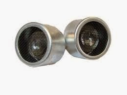
40kHz ultrasonic transducer


The recommended ultrasonic remote control circuit utilizes ultrasonic transducers to deliver and acquire the ultrasonic signals.
Ultrasonic transducers are being used in measuring the distance of an object and several other programs. In this circuit, we give them a try for another objective of generating a remote controlled relay.
Ultrasonic remote control receiver circuit


Working Of Circuit:
This project involves two parts i.e., transmitter circuit and receiver circuit.
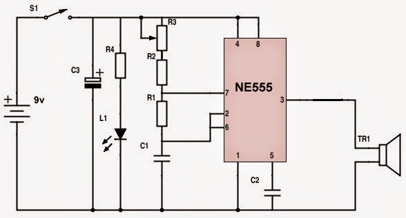
The transmitter circuit contains a 555 timer IC that may be the heart of the circuit. Here, the 555 timer is employed in astable multi vibrator mode. It may oscillate at a frequency of 40 - 50 KHz.
The ultrasonic transducer is utilized to transmit this frequency by using ultrasonic waves. A 9v battery enable you to power the transmitter circuit. The variable resistor R3 (in transmitter circuit) are often used to adjust the frequency.
The receiver circuit contains two essential levels for the processing of the ultrasonic waves obtained by the obtaining transducer.
The first level is a rectifier which amplifies the signals by using the transistors Q1 and Q2.
The improved and filtered DC is provided to the inverting pin of the operating amplifier CA3140. The inverted output is utilized to bias the transistor Q3 which encourages the relay and there goes the second stage.
The preset resistor R2(in receiver circuit) enable you to adjust the level of sensitivity of the circuit.
You can make use of a 9v SMPS power supply to power the receiver circuit.
The receiver circuit really should remain ON and a push-to-on switch can be employed in the transferring circuit to function as a remote.
Bring together the circuits on basic function PCB’s. You may surround the transmitter circuit in the right casing and the transducer, push-to-on switch and LED needs to be outside of the casing.
Ultrasonic waves are directional in nature and as a result, you must lead the waves straight onto the acquiring transducer for the relay to turn on.
Parts List for the above discussed ultrasonic remote control circuit:
Transmitter circuit:
- R1 – 18K,
- R2 – 10K,
- R3 – 5K variable resistor,
- R4 – 1K,
- C1 – 680pf,
- C2 – 0.01µf,
- C3 – 100µf, 25v,
- L1 – green LED,
- TR1 – ultrasonic transmitter,
- S1 – push-to-on switch,
- Receiver circuit:
- R1 – 10K,
- R2 – 5K variable resistor,
- R3- 10K,
- R4 – 15K,
- R5 – 100K,
- R6 – 10K,
- R7 – 4.7K,
- R8 – 15K,
- R9 – 10K,
- R10 – 12K,
- R11 – 390K,
- R12 – 470K,
- R13 – 27K,
- R14 – 1K,
- C1 – 0.56µf,
- C2 – 0.1µf,
- C3 – 0.22µf,
- C4 – 10µf, 25v,
- D1, D2 – 1N4148,
- D3 – 1N4007,
- Q1, Q2 – BC 548,
- Q3 – BC 558,
- Q4 – SL 100,
- RY1 – 9v relay,
- RX1 – ultrasonic transmitter