

A Wien bridge oscillator is an electronic oscillator design to create sinusoidal waves. The circuit is able to manufacture a comprehensive range of frequencies.
The wien bridge oscillator is actually constructed around a bridge circuit originally designed by the researcher, scientist Max Wien in the year 1891, with the initial purpose of measuring impedances. The bridge consists of 2 pairs of resistors and a pair of capacitors. The oscillator also works like a positive gain amplifier with the aid of a bandpass filter that positioned like a positive feedback network.
How it Works
As seen in Figure below, the Wien-bridge oscillator produces low-frequency sine waves and works without large inductors. The frequency-deciding components for that oscillator circuit are a pair of resistors and capacitors, each.

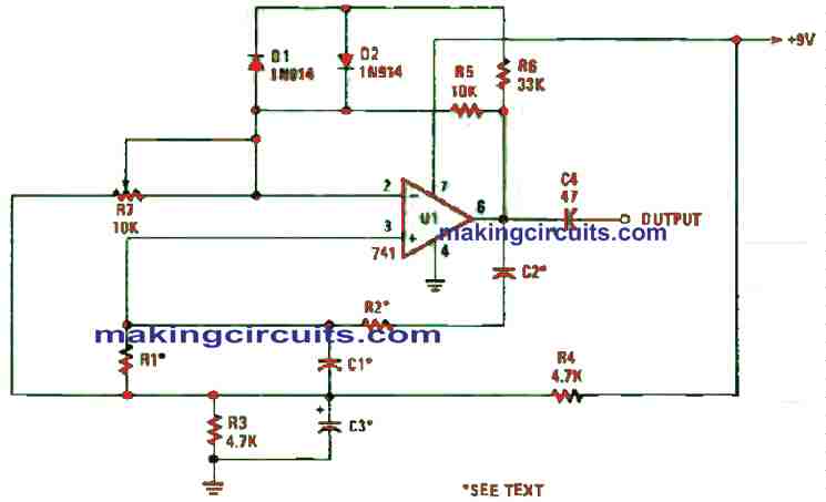
This Wien-Bridge oscillator could be built by employing a single active element, which is the famous 741 op-amp.
The IC sets the gain using the values of R5, R6 and R7 as well as the non-linear properties of diodes D1 and D2. The fine gain control, R7, configures the op-amp’s gain to generate a fresh sinusoidal output waveform.
Wien-Bridge Frequency
The frequency of the wien-bridge oscillator is dictated by the values of R1, R2, C1 and C2. The resistances and capacitances have the same value under their properties.
It is a little bit challenging to configure the frequency of the Wien-bridge oscillator. Let’s assume a frequency of 1 kHz is required and two 5% 0.005 µF capacitors are available, the resistance can be calculated using this formula:
R = 0.159 / fC
Plugging in the values will give a resistance of 31 kΩ. The closest resistor values to this is the 30 k or the 33 k one. If you can get your hands on a pair of 1 µF Mylar or polyester capacitors, or even construct your own by paralleling two 0.5 µF units for C1 and C2, you can produce really low-frequency sine waves.
A pair of 100 kΩ resistors for R1 and R2, and the two 1-µF capacitors for C1 and C2 will make the circuit to oscillate at around 1.6 Hz. When you increase the resistor values to 1 MΩ, the oscillator will decrease to about 0.16 Hz.
A Simple Sinusoidal Oscillator using Phase Shift
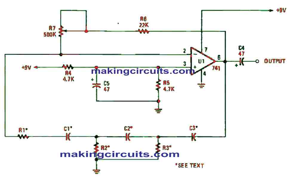
This oscillator circuit produces a sine wave by using three capacitors with identical values and resistors in a phase-shift setup, as shown in Figure 5. A 741 op-amp delivers amplification to compensate the losses in the RC phase-shift network and a half of the phase shift is required to retain oscillation.
The op-amp’s gain is set by the values of R6, R7, and R1. You can use values R6 + (R7/R1). At a gain of 30, the oscillator will generate a decent sine-wave output. Every time the values of R1-R3 are altered, you must re-adjust the op-amps’ gain.

Calculating the Frequency
The frequency of the phase-shift oscillator can be easily set just like the one from the previous experiment. However, pay attention to the different formula in use.
F = 1000000/2π X √6RC
In simpler terms, the formulas to compute the frequency, resistance and capacitance are:
f = 65 k / RC
R = 65 k / fC
C = 65 k / fR
Let’s say we have three 10 k resistors and three 0.068 µF capacitors, we can determine the frequency by applying one of the above formulas and get 95.5 Hz as our frequency.
Always remember to plug in the values you’re dealing with so that you’re better familiarized to them.