

The post details a simple IC 555 based NiCd charger circuit which can be used for charging all types of nickel cadmium batteries with great accuracy.
Charging a 12 V NiCd battery by a 12 V source is a futile attempt as the charging voltage must always be higher than the nominal one. So a 12 V battery will need a 14 V source.
Circuit Description
This NiCd charger circuit is basically a voltage doubler created using the 555 IC. The oscillation of the IC alternatively connects the output to earth and the +12 V supply voltage.


At logic low of pin 3, D2 and D3 charges C3 to nearly 12 V. the voltage at the junction of C3 and D3 doubles to almost 24 V when pin 3 is at logic high.
This happens because the capacitor C3 is charged to around 12 V as its negative terminal is at +12 V. Then D3 gets reverse biased while D4 keeps conducting, which charges C4 to just over 20 V, sufficient for our needs.
The 78L05 at IC2 is the current source here. It tends to maintain the value of 5 V for its output voltage Uo, that manifests across R3. Io is obtained as follows:
Io = Uo/R3 = 5/680 A= 7.4 mA
The 78L05 has its own current consumption too, drawing about 3 mA from the central terminal. The load current thus cumulates to about 10 mA, which works for charging NiCd batteries.
The LED was added as an indicator for the active charging current.

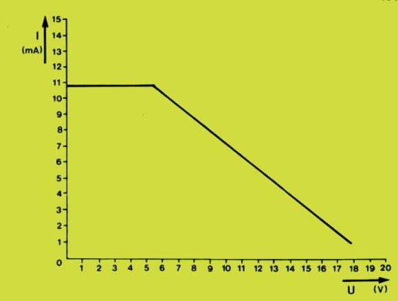
The graph of the charging current plotted against the battery voltage as seen in Figure 2 indicates an imperfect current, since a 12 V battery is charged by a meager 5 mA current. The reasons for this are:
· As the current increases, the output voltage of the circuit shows a tendency to fall.
· The voltage drops by 5 V across the 78L05 and there is a further drop of 2.5 V that the IC requires.
· The LED also causes a 1.5 V drop.
Despite all this, a 5 mA current can continuously charge a 12 V NiCd battery with a 500 mAh rated capacity.