


The submit offers an industrial water level controller with drain timer circuit.

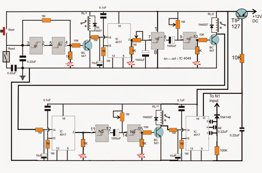
Talking about offered tank fill/drain sequence controller circuit diagram, when power is very first used at the emitter of the PNP 2N2907, its base capacitor briefly permits it to perform until pin10 of the bottom-right 4017 latches the base of the transistor into a long term conduction method.
The circuit right now gets latched and powered.
All the 0.1uF capacitors associated with the pin14 of the 4017 make sure that the IC becomes reset and in a standby position with their appropriate outputs held at a "0" logic. This guarantees that most of the relays stay in a deactivated position at power turn on.
Additionally, the input capacitor of N1 resets N1/N2 into a negative latch to ensure that the output of N2 starts with a logic zero maintaining the relay close off.
Right now when the "start" button is pushed, N1 negative latch is reverted to a positive latch producing a positive at the output of N2 which often triggers RL1, turning on the motor solenoid inlet valve that could be associated across its N/O contacts and mains.
The inlet valve maintains water running in the tank until it gets to the specific threshold, activating the reed relay into a closed position. This steps one more time grounds the N1 input by means of the series capacitor reverting the N1/N2 latch to its original negative condition. The inlet valve here gets turn off.
Shutting off the above relay transistor brings about an optimistic pulse to appear at pin14 of the connected IC 4017, which replies by shifting its output high logic from its pin3 to pin2, pin2 now turns into high which starts charging the input capacitor of N3 via the 1M setting until after the fixed delay the capacitor evolves into fully incurred leading to a high logic at the input of N3.
N3 reacts by producing its output low which inturn forces the input of N4 to turn out to be low and its output high....toggling ON the hooked up relay driver stage. This is linked to the water pump and keeps it turned on until the input capacitor of N4 charges fully, reverting N4 output to zero and shutting off the motor. This delay is dependent upon the 1M pot at the input of N4.
The switching OFF of the above relay transistor leads to the next IC 4017 to push its logic high to its pin2 which quite exactly the same is associated with the N5/N6 timing sequence activating RL3 and its connected drain solenoid but only until the N6 capacitor gets fully imposed in which the relay shuts off after a delay set by the N6 1M pot
The above switching exactly like in earlier phases affects the last IC 4017 which transfers a logic high at its pin2 activating a temporary high logic at the input of N1, one more time reverting its latch to a confident mode, simulating the pressing of the commence switch....the method commences over again, and repeats for 3 times until a high logic is forwarded to pin10 of the bottom right 4017.
This high logic blocks the PNP 2N2907 conduction breaking the power supply to the circuit via the PNP, immediately switching OFF the entire circuit into a stand still.
The power now really should be turned OFF and activated again to be able to bring back the circuit in a standby position.
RL1 = Activates water solenoid
RL2 = Starts 220V water pump (2 min ON delay is adjusted by N3 pot, "t" minutes ON is determined by N4 pot)
RL3 = Opens drain solenoid (t1 is set by adjusting N6 pot)
