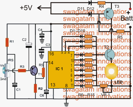
Right here we talk about a an emergency lamp circuit consisting of an infrared remote controlled brightness control feature.
Talking about the schematic of the suggested LEd emergency lamp circuit with infrared remote dimming feature, the design essentially includes three phases: the infrared toggled 4017 sequencer, the LED dimmer utilizing T2, and the automatic emergency switch making use of T3.
The IR sensor is a regular TSOP series IC set up with a BJT buffer T1 which amplifies the output from IRS sensor each time its toggled with an external IR remote transmitter, which might be easily your TV remote control handset.
The above switching reply is correctly utilized at the clock input of the IC 4017 which can be a Johnson divider counter chip and turns into to blame for producing a sequencing positive high shifts across its pin3 (start) to pin (11) and back to pin3 (repeat).
Each of he above 10 sequencing high outputs are shut down via 10 individual rectifier diodes and a series resistor. The resistors are determined so as to produce a correspondingly incrementing potential difference at the base of T2 referring to the value of the resistor set by VR1 across the base and ground of T2.
Based upon which output of the IC4017 might be high at any presented instant, the associated LED brightness is identified in accordance with this chosen output (toggled via the IR stage and the remote handset). At pin3 the illumination could be the highest while at pin11 it may well set to generate the minimum brightness over the connected LED.
T3 is located to invert its collector voltage in accordance with the input at its base obtained from an external AC to DC 5V adapter unit.
The moment this supply is taken away or goes wrong, T3 switches ON via R5 enabling the needed battery voltage to reach the collector of T2, which inturn passes it on to the LED hooked up across its emitter/ground terminals with the needed amount of glow as dependent upon the particular output of the IC 4017 at that immediate picked to be high by the user employing the IR remote control facility.
Parts list for the above IR controlled LED emergency lamp with dimmer circuit
R1, R3 = 100 ohms,
R2 = 100K,
R4 = 4K7,
R5 = 10K,
R6---R15 = 200 ohms to 2K (proportionately incremented)
VR1 = 10k preset
C2 = 47uF/25V
C1, C4= 22uF/25V,
C3 = 0.1, CERAMIC,
T1 = BC557B
T2 =TIP122
T3 = TIP127
ALL DIODES ARE = 1N4148,
LED = 1 watt high bright
IC1 = 4017
Battery = 4V/4AH or bigger
