


This cool solar-powered LED light trap is made to attract insects at night. It uses a bright light to pull these pests away from important crops helping to protect the plants from damage. The idea for this circuit came from Mr. Manik who had some specific requests for how it should work.
Here are the main features:
The device automatically turns on the LED light at sunset and can stay on for 2 to 4 hours which helps catch harmful insects that might harm a field.
It has a small 3W solar panel that charges a battery really well during the day.
This solar panel can charge a battery that holds between 1500 and 1800 mAh.
When night falls the device lights up a LED strip using power from the battery with a power range of 1 to 3 W.
You can set the light to stay on for either 2, 3, or 4 hours using a microswitch and it will turn off by itself afterward.
To keep the battery in good shape, the device is built to stop overcharging and to prevent it from running too low.
There’s also a manual switch so you can turn the lights on and off whenever you want.
Choosing affordable parts is important because the plan is to use many of these devices.
Lastly the design needs to be weatherproof since it will be used outside in fields.
Circuit Description
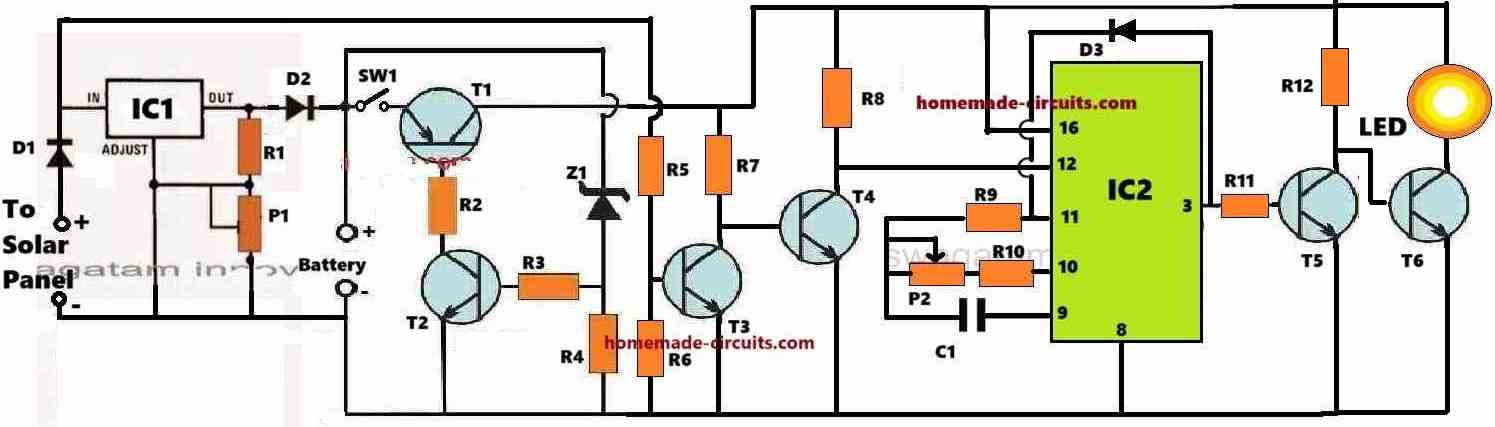
The whole circuit schematic for our timer-equipped solar LED light bug trap circuit is displayed in the accompanying image.

Parts List
Resistors (1/4 watt, 5% CFR)
| Component | Value |
|---|---|
| R1, R2 | 120 Ohms |
| R3 | 1k |
| R4, R6 | 4.7k |
| R5, R11 | 10k |
| R7, R8, R10 | 100k |
| R9 | 2.2 Meg |
| R12 | 1k |
Presets/Potentiometers
| Component | Value |
|---|---|
| P1 | 4.7k preset |
| P2 | 1 Meg preset or pot |
Capacitors
| Component | Value |
|---|---|
| C1 | 2uF/25V non-polar |
Semiconductors
| Component | Type |
|---|---|
| D1, D2 | 1N5402 Diodes |
| D3 | 1N4148 |
| Z1 | 6.9V 1 watt zener diode |
| T1 | TIP32 Transistor |
| T2, T3, T4, T5 | BC547 Transistors |
| T6 | TIP122 Transistor |
| LED | 3 watt LED strip |
ICs
| Component | Type |
|---|---|
| IC1 | IC LM317 |
| IC2 | IC 4060 |
Power Components
| Component | Specification |
|---|---|
| Battery | 7.4V 2000 mAh Li-Ion |
| Solar Panel | 12V 1 A solar panel |
Looking at the diagram above you can really understand how the solar LED insect trap circuit works by thinking about these important points:
Solar Regulator and Battery Charger
The diode D1 is connected to the positive side of the solar panel. This helps protect against any accidental reversal of polarity that might happen with the solar panel.
The integrated circuit IC1 which is the LM317 model, is set up to act as a voltage regulator for the solar panel. Its main job is to provide a steady and controlled direct current output which is super important for charging the battery properly.
The adjustable preset P1 is set to make sure that the voltage going to the battery stays just below its maximum charge level. This careful setting is really important because it stops the battery from overcharging, which helps it last longer.
For this project it's best to use a 7.4V 2000 mAh lithium-ion battery.
When using a 7.4V lithium-ion battery, the highest charge voltage is about 8.4V. So the preset P1 should be adjusted to give an output of around 8.2V at the battery terminals.
Alternatively you could swap out the adjustable preset P1 for a fixed resistor that is carefully calculated to keep the voltage at exactly 8.2V across the battery.
Choosing to set the maximum charge level a bit lower than the full capacity is a smart move to protect the battery from the dangers of overcharging.
The Low Battery Monitoring and Cut-off System
The setup that includes Transistor T1, Transistor T2, and Zener Diode Z1 works together to monitor the battery and cut it off when needed.
As long as the battery voltage stays above a certain level set by Zener Diode Z1, Transistor T2 keeps working, which means Transistor T1 also stays on.
When T1 is on it can supply power to the rest of the circuit connected to it.
But if the battery voltage drops too low, below the level that Z1 has set, the Zener Diode will turn off, cutting off the power to T2.
This means T2 stops working, and T1 also turns off.
When T1 is off the whole circuit shuts down protecting the battery from running out of power or getting damaged.
The Circuit for Sensing Darkness
In our insect light trap circuit, the parts T3 and T4 work together to sense when it gets dark. As long as the solar panel produces more than 0.6 V, T3 stays on which keeps T4 turned off.
With T4 off, the timer circuit known as IC 4060 doesn’t work and stays inactive.
The Timer Function
The timer is based on IC2 which is a standard 4060 timer oscillator chip.
As long as T4 is off—meaning it’s still light outside—pin #12 of IC2 stays high because of resistor R8.
When it gets dark enough and the solar panel stops producing voltage T3 turns off which then turns T4 on.
Now that T4 is on, pin #12 of IC2 connects to ground turning on IC2 and starting its internal clock to begin counting.
While it counts the output at pin #3 of IC2 stays at a logic level of 0 keeping transistor T5 off and allowing transistor T6 to turn on. This makes T6 light up the LED lamp.
In short when it gets dark, the timer IC2 starts working and while it counts the LED stays lit.
The LED lamp has started attracting different wild insects which can harm the health of the field crops.
This LED lamp keeps the insects busy making them fly and hover around it, which helps to keep them away from the crops.
After a set amount of time, based on the settings of P2, the time for IC2 ends causing pin#3 to go high and turn on T5. When T5 turns on, T6 turns off, which switches off the LED lamp.
IC2 stays in this position, held by diode D3, until the next morning when T4 turns off allowing IC2 to go back to its original state.
The Timer Stage is Unnecessary
Looking at the points mentioned, it’s clear that the timer stage linked to IC2 is not needed.
This is because we already have a low battery cutoff system that makes sure the battery doesn’t go below a certain level.
So the LED will automatically turn off after a certain time when the battery voltage drops below the set low voltage limit.