


Here we' are going to build one of those popular LC-based oscillators, the Colpitts oscillator.
What's Oscillators?
Electronic oscillators are all over the place, showing up in most of the electronic stuff we use every day, from your basic digital clock to those high-end core i7 processors. Oscillators are the heart and soul of all digital circuits. But it's not just digital circuits that use them; analog circuits use oscillatory circuits too.
Take AM and FM radios for example. They use a high-frequency oscillation as a carrier signal to, like, transport the message signal.
There are tons of different kinds of oscillators out there, like RC, LC, crystal, and so on. Each one has its own perks and drawbacks. So there's no such thing as the "best" or "ideal" oscillator. You gotta look at the situation in your circuit and pick the one that fits best. Thats why you see so many different kinds of oscillators in everyday gadgets.
LC Oscillators:
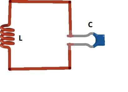
The LC oscillator has an inductor and a capacitor, plain and simple. The LC oscillator makes use of positive feedback for generating the oscillations in the circuit. It doesnt need an AC signal from the outside to start oscillating, unlike some other amplifiers.

So the value of the capacitor and inductor decides what the output oscillation will be. But how do these things actually make oscillations happen?
Well, we got to put some supply between L and C, like voltage. When we give it some voltage, the capacitor gets charged up. And then when we cut off the supply, the energy stored in the capacitor flows over to the inductor and the inductor starts making a magnetic field around itself until the capacitor is totally empty.
Once the capacitor is all discharged, the magnetic field around the inductor collapses. This collapsing field induces voltage and charges up the capacitor again but with the opposite polarity. And then the whole cycle starts over.
This charging and discharging thing between L and C makes oscillations and we call this oscillation the resonance frequency. But heres the thing, the frequency generation won't last forever 'cause of something called parasitic resistance. This resistance eats up the energy in the oscillatory circuit by turning it into heat. Bummer, right?
To keep the oscillation going and use it with a decent output strength we need an amplifier that gives us zero-degree phase shift and feedback.
The feedback takes a little bit of the output from the amplifier and feeds it back to the LC network. This compensates for the energy loss caused by the parasitic resistance and keeps the oscillation going. And that's how we can get a nice, steady sine wave output!
Application Circuit:
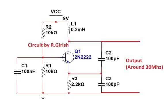
Heres a Colpitts oscillator circuit that can pump out a signal around 30 MHz. Let's learn more...

So two things basically are super important to keep the oscillations going in transistorized LC resonant crystal oscillator circuits. First the feedback voltage coming from the transistor collector needs to be in phase with the actual input voltage thats initially hitting the base of the transistor.
In other words, the feedback link in the circuit has to be positive or regenerative. You want that energy adding to the signal, not canceling it out!
Second, the amount of feedback energy reaching the base network has to be strong enough to make up for the energy losses happening in the base circuit. We might need to talk about the theory of Q before we can really get into how oscillators work.
Q is basically a measurement of quality in a resonant circuit. Its like reactance divided by resistance and the Q factor shows how well the circuit can keep oscillations going with the least amount of feedback.
Basically the bigger the Q, the better the resonance stage of the circuit is at doing its job. A quartz crystal can have a crazy high Q, like 10 million at 1 MHz!
Even though the Q magnitude for a connected resonator crystal drops to somewhere between 20,000 and over a million, it's still way higher than what you'd get with a regular LC resonator or LC tank circuit.
LC Oscillator with Crystal
The super high Q of the crystal oscillator really cuts down on frequency drift caused by temperature and DC voltage changes.
Plus the crystal-controlled oscillators make less noise compared to regular LC tank-based oscillator circuits, which means they give you a cleaner output signal. The simplest crystal oscillator is made with a single BJT and a basic feedback network.
Figure 1-a below shows a block diagram of a universal crystal oscillator. In this setup you can see an NPN BJT-based amplifier configured with three feedback circuits. We're assuming there's proper DC bias in place, even though it's not shown in the diagram.
The next Figure 1-b is a comparable circuit built with the parts L1, C1, and C2, as shown. All of the crystal oscillator circuits we're gonna talk about are designed to work with the same basic layout, using at least two capacitors and an inductor. And the crystal is part of the feedback circuit.

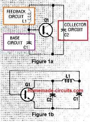
so those capacitors C1 and C2, well they're basically made up of whatever leftover transistor stuff and junction capacitance is hanging around. And capacitor C2 is almost like a parallel network, like when you put an inductor and a capacitor together side-by-side.
Now this LC combo? It's kinda like a bouncer for the crystal's third overtone, picking only that one, because it only acts like a capacitor when the crystal is vibrating at that overtone frequency. But when the crystal is vibrating at its fundamental frequency, it acts all inductive.
So putting an inductor at C2 is like telling the crystal to operate at its fundamental frequency and not oscillate there. Besides needing to make the signal bigger (amplification) and looping it back around (feedback), an oscillator circuit also needs something to stop it from going totally wild.
Thats where the limiting factor comes in – when the input signal gets bigger, the output signal eventually stops getting bigger too. Because of that, the oscillator's output stops and just stays there.
The usual Colpitts crystal-controlled oscillator? Super picky about the load and needs just the right tuning. But these two "sorta separate" (semi-isolated) versions are easier to work with, so they're a better choice if you just want something that works.
Now if you need the frequency to be like, super accurate, then the Pierce crystal oscillator is what you should grab.
But if you're just testing around with oscillators, you might find that the Butler circuit can actually oscillate even without a crystal! So you can try it out with or without a crystal and see what happens.
General Colpitts oscillators
So in this section, we're gonna talk about a couple of ways you can build a Colpitts crystal-controlled oscillator: the regular one and the sorta-separate one (semi-isolated).
The regular one which you can see in Fig. 2, is really sensitive to the specs of both the crystal itself and the load resistance. Plus it can only put out like, less than half of the power the crystal can handle (crystal's power dissipation). But even with all that it's still a pretty popular choice.

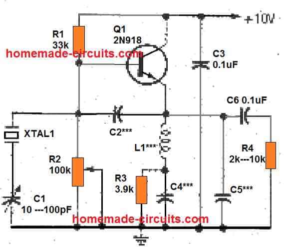
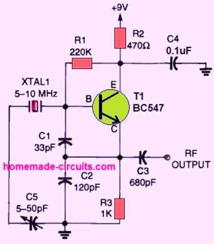
Remember, when you're using a fundamental crystal, you' are going to get frequencies that range from like, 1 MHz all the way up to 30 MHz.
But if you are using a third-overtone crystal then you're looking at frequencies from 35 to 60 MHz. And heads up – the values for C2, C4, and C5, those should be in picofarads, and the value for L1 should be in microhenries, just so you know.
Now these resistors R1, R2, and R3, their job is to give the transistor Q1 its DC bias, to get it going. And that little potentiometer R2, That is there so you can get up to around 1.5 milliamperes of emitter current.
Then you have got the capacitors C3, C4, and C6. Those act like bypasses for the radio frequency when XTAL1 is doing its thing at its working frequency whether that's the fundamental or the overtone.
And Capacitor C2, that acts like the feedback base circuit, and it's basically the same as capacitor C1 like we talked about in Fig. 1. Now when this whole thing is running at XTAL1's operating frequency, L1 and C5 end up acting like a net capacitive reactance so they work just like the collector circuit feedback capacitor kinda like C2 in Figure 1.
But when you are using those overtone crystals, L1 and C5 become like a bouncer for the overtones, making sure the crystal doesnt oscillate at its fundamental frequency. And then you have got the Capacitor C1 which is an adjustable trimmer and it tweaks the feedback from L1. Basically if you make the value of C1 smaller, the oscillator's output frequency goes up.
Another Crystal Controlled Colpitts Oscillator
Okay so next up is this thing called a tapped capacitor setup but you might also know it as a Colpitts oscillator circuit. Its controlled by a crystal, naturally. And the amount of feed-back ratio you need to keep the whole thing oscillating? That's decided by the values of C1 and C2. and C2.

Now the capacitors, C1 and C2, you must pick their values carefully for whatever frequency you' are aiming for. That's how you get the best output and keep the frequency nice and stable.
But you will need to play around with it a bit, experiment a little, you know? But experimental research is actually pretty fun and it's a good way to learn stuff!
Simple RC Oscillator Circuit
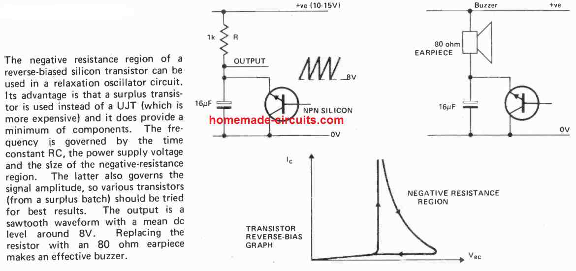
Now get this, you can even build an oscillator using just a resistor and capacitor network, plus a transistor, of course. In this setup you dont even connect anything to the transistor base terminal, you just use the emitter and collector.
You can check out the complete circuit diagram for this RC oscillator in the picture below:

Simple LC RF Colpitt Oscillator
A basic LC RF oscillator, the Colpitts circuit shown in the accompanying diagram operates well at frequencies between approximately 100 kHz and 50 MHz or higher.
The transistor TR1 is set up as a source follower, and the small coupling through the T1 inductor winding is used to produce positive feedback and increase the voltage needed to keep the oscillation going.

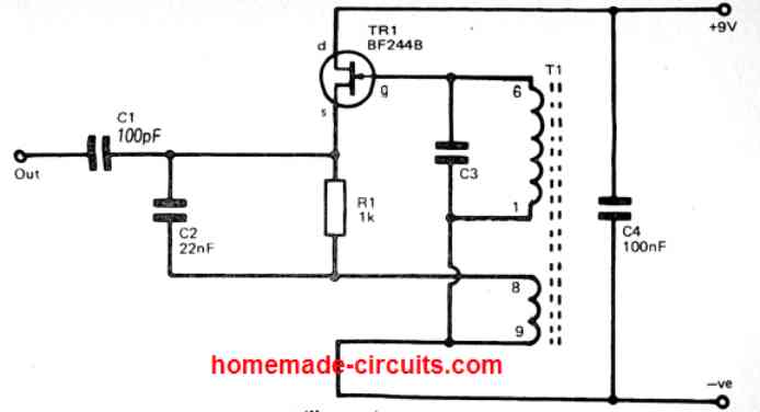
The primary winding of T1 along with C3, they team up to make this LC tuned circuit. This combo is what sets the operating frequency of the LC oscillator circuit. Now R1 is like the source load for TR1 at the DC thats supplied but then TR1 gets a bypass with AC through C2. This makes the coupling winding of T1 the real source load for TR1.
The output signal from the oscillator is taken from the TR1 source through the DC blocking capacitor C1. And that Capacitor C4 is just hanging out as a supply decoupling capacitor. Now if you want to be able to tweak the tuning of the oscillator, you could swap out C3 for a variable capacitor or maybe use a mix of fixed and variable capacitors to get the range you want.
For LC oscillators that run at medium and high frequency, a lot of hobbyists these days just buy those ready-made coils. They usually give you better and more predictable frequency outputs than if you try to wind your own.
If you wanna build T1 yourself at home, just wind two sets of coils (6 to 1 and 8 to 9) one on top of the other around a little ferrite rod. You can play around with the number of turns to get different frequency outputs.
The really important thing to remember is that you got to connect that smaller coupling winding with the right phasing. If you don't, then the circuit won't oscillate! But the best way to figure out the right way to hook up that smaller coil is just to try a few things and see what works.