


A short circuit in a house wiring can occur to be an issue that takes place extremely rarely and people aren’t too considering to get any appropriate preventive measure set up in their houses and take the hazard very casually. In spite of this occasionally as a result of some accidental fault, a short circuit in the mains wiring results in being unavoidable and it the occurring leads to a disaster and massive . Sometimes the outcome results in fire risks as well as of living and property.
Caution - THE PROPOSED mains short CIRCUIT breaker IS NOT ISOLATED FROM MAINS POTENTIALS, SO Tremendously Harmful TO TOUCH IN UNCOVERED POSITION AND WHEN POWERED.
Even though various kinds of short circuit breaker units are presented ready made available in the market, these are definitely very expensive. Furthermore an electronic hobbyist will usually need to make such an equipment all by him and enjoy its display in the house.
A short circuit breaker circuit explained in this post is definitely a piece cake as far rendering it is troubled and once mounted will give you a lifespan longer security against all short circuit like problems which may inadvertently occur. The circuit may also protect you house wiring against a likely overload problems.

Circuit Description
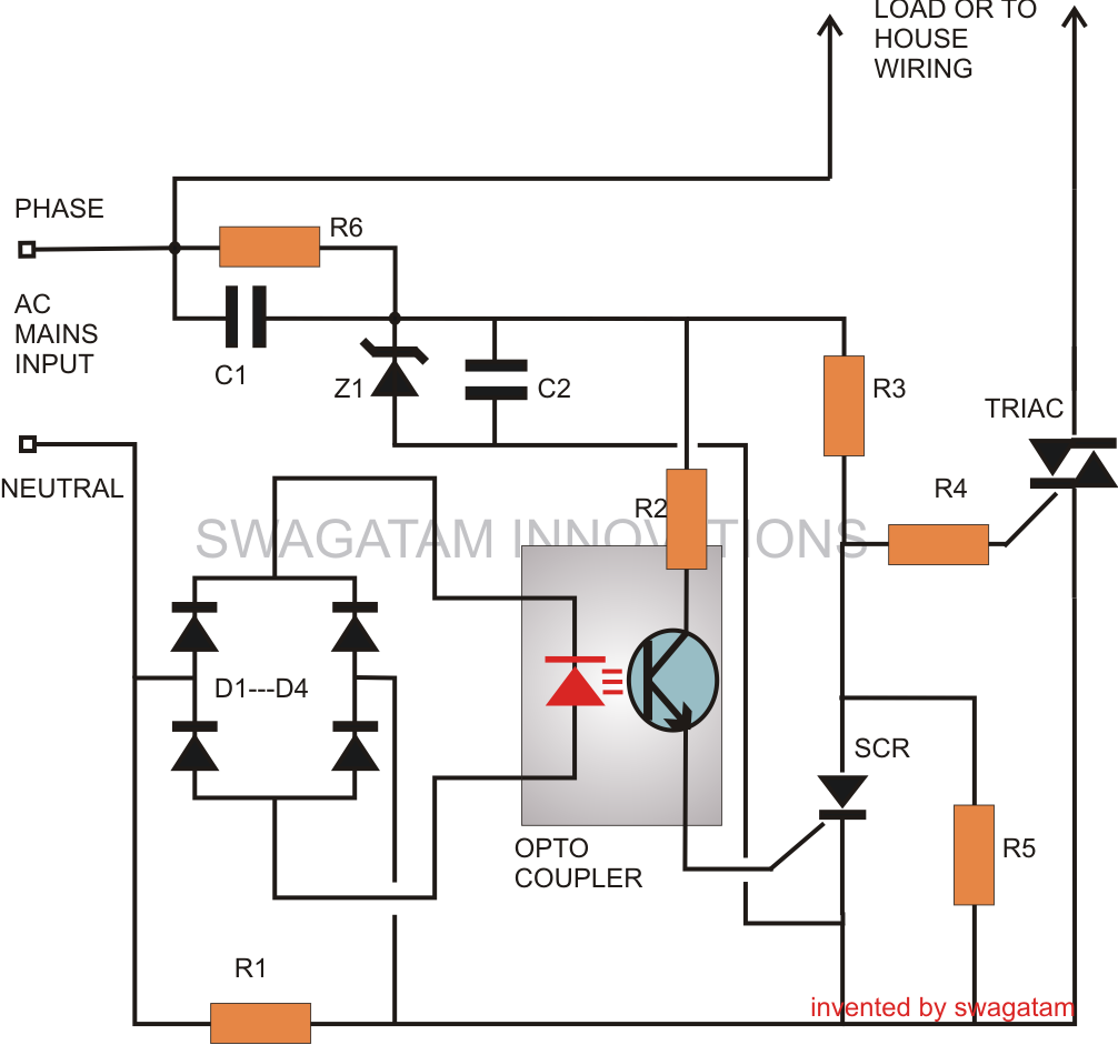
The short-circuit protector circuit demonstrated in the schematic appears fairly uncomplicated and might be verbally simulated given below:
The sensing phase of the circuit in reality turns into the heart of the whole process and contains an opto-coupler OP1.
Normally we understand, an opto-coupler internally contains an LED and a switching transistor design, the transistor is turned on as a reaction to the lighting of the built-in LED.
Thus the initiating of the transistor which forms the output of the device occurs without having physical or electrical contact rather by means of the passage of light rays from the LED.
The LED which turns into the input of the device might be switched by means of some external agent or a voltage source which needed to be held aloof from the output stage of the opto-coupler.
In our circuit, the opto coupler LED is powered by means of a bridge network which receives it voltage source from the potential produced across resistor R1.
This resistor R1 is attached in such a way that the AC mains current to the house wiring transmits through it thereby any over-load or over-current is subjected over this resistor.
In the course of an over load or short circuit situations, the resistor immediately builds up a potential across it, which can be improved and delivered to the opto coupler LED.
The opto LED instantly lights up, turning on the corresponding transistor.
Talking about the circuit we observe that the opto transistor’s emitter is linked to the gate of an external SCR, whose anode is further more linked to a Triac's gate.
All through regular problems, the triac stays turned on, enabling the load linked across it to remain operating.
Such things happen simply because the SCR stays turned OFF and enables the triac to acquire its gate current by means of R3.
In spite of this in the instance of an over load or a short circuit, as mentioned previous, the opto-coupler transistor carries out and causes the SCR. This promptly pulls the gate potential of the triac to ground, preventing it from carrying out.
The triac instantly turns OFF, preserving the load and the house wiring to which it is set up.
The SCR remains latched, until the problem is improved and the circuit is restarted.
The section consisting C1, Z1, C2 is an easy transformerless power supply circuit, useful for powering the SCR and Triac circuit.
Parts List
- R1 = iron coiled wire; its resistance is calculated to generate 2 volts across it at the determined critical load circumstances.
- R2, R3, R4 =100 Ohms
- R5 = 1K,
- R6 = 1M,
- C1, C2 = 474/400V
- SCR = C106,
- Triac = BTA41/600B
- Opto-Coupler = MCT2E,
- ZENER = 12V 1W
- Diodes = 1N4007