


In this article I will explain a few exciting and compact light chaser circuit that operates on both 220V and 120V power sources. This circuit enables us to light up lamps or bulbs connected to 220V mains in a delightful sequential chasing pattern, making it an ideal choice for adding a festive touch to our celebrations!
Technical Specifications
One of the standout features of this light chaser circuit is its adjustable chasing effect, thanks to potentiometer controls. This flexibility makes it a superb option for decorative lighting during special events like Christmas and Diwali.
A special shoutout goes to Mr. Ashly, whose request inspired this creative project!
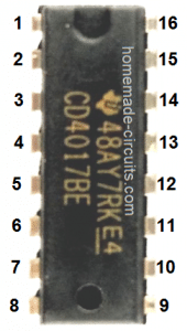
As is common with these circuits, our Diwali and Christmas light chaser utilizes the popular IC 4017. This compact chip functions as a divide-by-10 Johnson counter or divider IC, enabling us to achieve that captivating chasing effect.
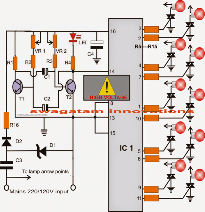
The IC boasts ten outputs that illuminate in a specific sequence: 3, 2, 4, 7, 1, 10, 5, 6, 9, and back to pin 10. By sending voltage pulses to pin #14 of the IC, we can create this dynamic output shift.
Here’s where it gets even more intriguing: we can connect these outputs to either LEDs for a stunning illuminated chasing effect or to triacs, allowing us to control our 220V mains-operated lamps or incandescent bulbs in the same entertaining manner as illustrated in the diagram below.
Circuit Working
Examining the circuit diagram, we see that IC1 is clocked or pulsed at pin #14 through a transistorized astable multivibrator stage. This setup generates alternating high and low pulses at its collectors, which we can observe in action with a blinking red LED.
Each time a high pulse occurs or the red LED blinks, the output from IC1 advances to the next output pin in the sequence. This process continues with each pulse sent to pin #14. Once the output reaches pin #11, the IC resets and starts the cycle anew at pin #3.
Since we’ve connected the outputs to the gates of triacs, those triacs will conduct in the same sequence as the IC outputs. This means our AC lamps will light up in that running or chasing pattern we’re going for.
If we want to change how fast this chasing effect happens, all we need to do is adjust the two pots VR1 and VR2 accordingly. It’s super easy!
Important Safety Note
This circuit works straight from mains power through a capacitive power supply which means it is not isolated from potentially dangerous mains current. So please remember to exercise extreme caution when testing or handling this circuit while it’s exposed. Safety first!
Circuit Diagram

Please be advised that there is no mains isolation available. It is imperative to exercise extreme caution to prevent the risk of electric shocks and potential fatal consequences.
Parts List
| Component | Specification |
|---|---|
| R1, R2, R3, R4, R5 - R15 | 1K |
| VR1, VR2 | 100k |
| C1, C2 | 10uF/25V |
| C3 | 474/400V |
| C4 | 100uF/25V |
| D1 | 12V zener, 1 watt |
| D2 | 1N4007 |
| R16 | 10 ohms, 2 watt |
| Triacs | BT136 |
| IC1 | 4017 |
| T1, T2 | BC547 |
| LED | Red, 5mm |
220 V Lamp Chaser using IC 7413


This circuit is designed to light up four 220V lamps in a sequential manner giving us that awesome 'running-light' effect that really catches the eye.
It includes a square-wave generator made up of T1 and IC1, along with a couple of shift registers which are IC2 and IC3, plus all the necessary stages to drive the lamps.
One of the cool features is that we can adjust the frequency of the square-wave using P1. This frequency can range anywhere from 0.1 Hz all the way up to about 10 Hz and the square-wave voltage is sent directly to the clock inputs of the shift register.
Now here’s how it works: when we press the S2 button it resets the flip-flops. This means that all the Q-outputs switch to '0' while the Q-outputs turn to '1' which effectively turns off all the LEDs and switches off those lamps. Once we let go of S2 we set S1 to position 1 which changes the input of the register to logic '1'.
Then with the next clock pulse that comes along the input data from the flip-flop gets transferred to the output, lighting up the first lamp. After that, we reset S1 to position 2. From there on each clock pulse shifts that logic '1' over to the next flip-flop while resetting the previous one.
This process lights up each lamp in sequence creating that dynamic chasing effect we’re looking for with our four 220V lamps.
220V LED Chasing Lamp for all Festivals
What we have here is a design that shows us how to create a really eye-catching solid-state LED light chaser that can operate directly from either a 220V or 120V AC power source. In this particular circuit the IC 555 generates a series of pulses at a frequency of 0.5 Hz and these pulses are fed into the clock input of the IC 4017.


The IC 4017 takes those pulses and responds by outputting a sequence of high logic signals across its pinouts 3, 2, and 4. This action powers the connected opto coupler in a sequential manner.
If we look at how the opto coupler outputs are set up we can see that they are connected to strings of LED lamps. These lamps light up one after another in response to the conduction of the opto coupler all while being powered directly from a 220V AC input through a transformerless power supply.
One neat feature of the MOC 3021 ICs is that they actually come with a zero crossing detector. This is super helpful because it helps eliminate any surge from the mains AC current that could affect the LEDs. Thanks to this, we can be sure that our LEDs will not burn out due to any sudden spikes in current.
Additionally the opto couplers play an important role in ensuring that while we are sequencing the lights, there is no RF noise generated during the switching action.
This straightforward transformerless LED chaser circuit is perfect for creating decorative LED string lights during festive occasions like Diwali and Christmas.
If we want to change how fast the sequencing happens all we need to do is adjust the value of the 220uF capacitor that is connected to the 555 IC.