


Ok, so here we see a very simple solar charger circuit that works without any ICs. We use only transistors and it automatically cuts off when the battery is full. This idea was asked by Mr. Alfred Newjohn.
What We Need This Circuit To Do?
Now let us see what the request is. You want a charger for a 12V 28.8AH lithium-ion battery which gets power from a 17V 4.5A solar panel (in full sunlight).
This charge controller must:
Stop charging when the battery is full (overcharge protection).
Disconnect the load when the battery is too low (low battery cut-off).
Be simple so beginners can make it.
Use only transistors and relays, no ICs or microcontrollers.
Use a Zener diode for voltage reference.
So now let’s see how we do it using just BJTs (Bipolar Junction Transistors)!
How This Circuit Works

Here we use two BJTs as voltage comparators to check the battery voltage and switch between charging mode and powering the load.
If you remember we have seen low battery indicators made using just two transistors and some resistors. This circuit uses the same idea to sense battery voltage and decide whether to:
Charge the battery from the solar panel
Disconnect the battery from the solar panel when full
Switch the battery to the load when needed
Step-by-Step Working Process
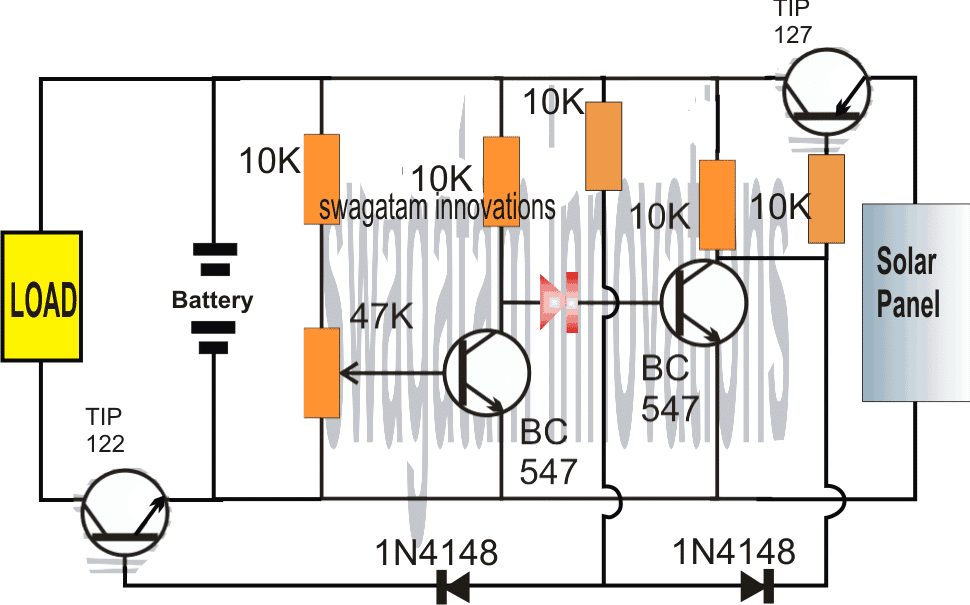
- When the Battery is Low
Suppose the battery is partially discharged.
Then first BC547 (left side) stops conducting because its base preset is set to this low voltage limit.
This makes the next BC547 conduct.
When this BC547 turns ON, then it activates TIP127 allowing the solar panel voltage to reach the battery and start charging it.
But at the same time TIP122 remains OFF so the load does not get power yet.
Result: Battery starts charging but load is OFF.
- As the Battery Gets Charged
The battery voltage rises as it stores energy from the solar panel.
Once it reaches the full charge threshold, then left BC547 starts conducting again.
This action switches OFF the right BC547 stopping TIP127.
When TIP127 turns OFF then solar panel stops charging the battery!
Now TIP122 gets activated slowly and the load starts getting power from the battery.
Result: Charging stops and load gets power.
Where Can We Use This?
Now this simple transistor-based solar charger can be used for:
Charging small Li-ion batteries safely
Solar-powered mobile chargers
Other small-scale solar applications
It is automatic so we don’t have to worry about overcharging or deep discharging.
Making the Charging Regulated
Ok now what if the solar panel voltage rises too much? We need to keep the charging stable.

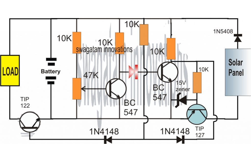
The next circuit version adds voltage regulation so that even if solar voltage increases, battery gets a fixed, stable supply.
This helps avoid overvoltage damage to the battery.
Alright, that’s all! Now you can build this super simple solar charge controller with automatic cut-off using only transistors.
PCB Design (Component Side)

Over-charge, Over-discharge Solar battery controller circuit:
The above designs can be further simplified, as shown in the following over-charge, over-discharge solar battery controller circuit:

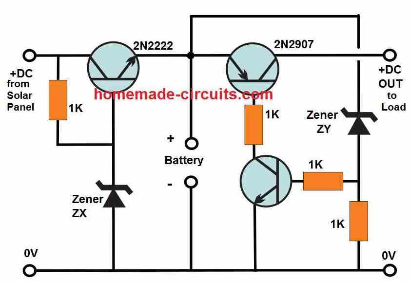
Here we got two zener diodes ZX and ZY both having their own special job to do in the circuit. First ZX is what decides when the battery has reached full charge and needs to be cut off from the charging source. The value of this zener diode is figured out using this basic formula:
ZX = Full charge battery voltage + 0.6V
So if our battery should be fully charged at 14.2V then ZX must be 14.2V + 0.6V = 14.8V. We may need to combine multiple zener diodes in series to get this exact value. If we still dont get the right voltage, then we can throw in a few 1N4148 diodes to fine-tune it.
Now ZY is the one responsible for stopping the battery from over-discharging. It works by cutting off the load when the battery voltage falls below a set minimum level. The ZY value is simply chosen to match this low-battery cut-off voltage.
For example if we dont want the battery to go below 11V then we just pick a 11V zener diode for ZY. Simple!
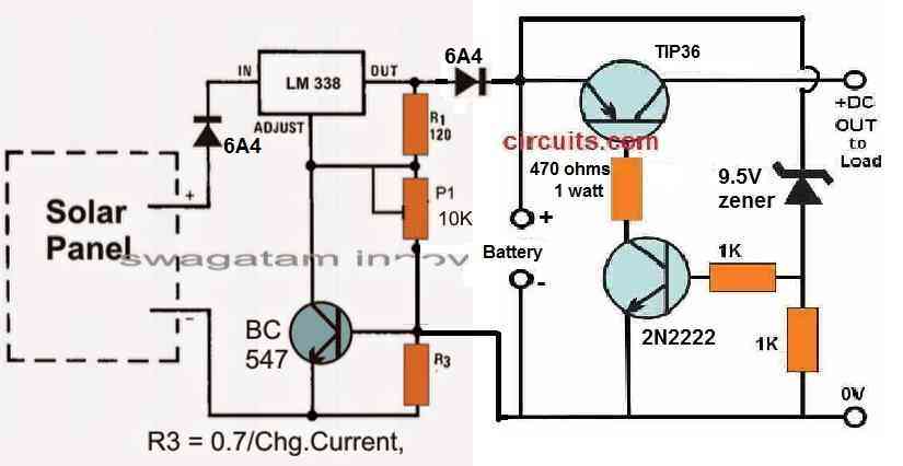
Improving the above Design with a Regulator LM338
Now if we want to improve this setup and add a proper regulated charging system, then we can hook up this circuit with an LM338-based charger, as shown in the second diagram. This LM338 regulator gives us guarantee that the battery gets a fixed, stable voltage even if the solar panel voltage is fluctuating.
So first, the LM338 regulates the charging voltage and current making sure the battery is not overcharged. Then the 2N2222 and TIP36 transistors take care of passing the charge to the battery and also keeping it safe from too much of discharge.
Now the moment the battery gets fully charged ZX gets activated and stops further charging. Likewise when the battery drains too much then ZY makes sure the load gets disconnected, preventing deep discharge.
Thats it! This is how we make a simple but effective solar battery charger with automatic cut-off, using just transistors and zener diodes, no microcontroller, no ICs (except LM338 if needed). Perfect for beginners, no complicated parts just a straightforward working circuit!
Parts List for the Solar Battery Charger Circuit
| Component | Specification | Quantity |
|---|---|---|
| Transistors | 2N2222 (NPN) | 1 |
| 2N2907 (PNP) | 1 | |
| TIP36 (PNP) | 1 | |
| Zener Diodes | ZX (Full Charge Cut-off) | As per battery voltage (e.g., 14.6V) |
| ZY (Low Battery Cut-off) | As per battery voltage (e.g., 11V) | |
| Resistors | 1K Ohm | 4 |
| 470 Ohm, 1W | 1 | |
| Voltage Regulator | LM338 (optional for stable charging) | 1 |
| Diodes | 6A4 (High current diode) | 2 |
| Battery | 12V, 28.8Ah Lithium-Ion Battery | 1 |
| Solar Panel | 17V, 4.5A | 1 |
| Heat Sink | For LM338 and TIP36 | 1 |
| PCB/Perf Board | As required |
How to Build This Solar Battery Charger Step by Step – No Confusion, Just Do It!
Alright so now let us see how we actually build this thing from scratch. We go step by step, no skipping, no guessing, just pure hands-on work, ok? You follow this, and you will get a working solar charger, no problems at all.
Step 1: Get All the Parts Ready Before You Even Think of Soldering
First things first, we don’t touch the soldering iron yet. We sit down and collect all the parts, otherwise halfway through we realize something is missing, and then a lot of waste of time! So get everything first. Check the parts list below and make sure all the components are in front of you.
Step 2: Prepare the Board – No Mess, No Clutter
No, we need a base where everything goes. You got two options:
PCB (Printed Circuit Board) – If you have a proper PCB design, great! Just print and use it.
Perf Board (General-Purpose Board) – If no PCB then we use a perf board and arrange components neatly. But we must plan how we place them, otherwise wires go all over the place like a spiderweb and troubleshooting becomes a nightmare!
Step 3: Start with the Small Parts – Don’t Rush!
Begin by soldering resistors and zener diodes (ZX, ZY) first. These are the smallest so they go first nice and easy.
Zener diodes must be placed correctly. They have polarity—one side must go to the right place or they won’t work. So check before soldering, ok?
No overheating! Soldering too long in one place can burn the part, and then nothing works.
Step 4: Time for the Transistors – Handle Carefully!
Now we put in the 2N2222, 2N2907, TIP36 transistors. These are important parts so we do not mess this up.
Check the pin configuration—every transistor has Base, Collector, and Emitter pins, and they must go in the right places.
Wrong pin placement = circuit won’t work. So double-check the datasheet if needed.
Step 5: If Using LM338 then Mount It Properly
If we want stable charging, we use LM338 voltage regulator.
This thing can get hot, so we attach a heat sink, otherwise it will fry itself!
Again, proper wiring is key. The IN, OUT, and ADJUST pins must be connected correctly or no charging will happen.
Step 6: Connect the Battery and Solar Panel – No Reverse Polarity or Boom!
Battery connections must be correct. If we mix up the + and – terminals then we are in big trouble.
Same for the solar panel input—check the polarity before connecting.
Once again, before powering up, double-check everything! Mistakes here can kill components instantly.
Step 7: Power It Up and Test – No Blind Guessing!
Before we even think of plugging in the battery and solar panel, we take a multimeter and check all connections.
We check if the battery charges and stops at full level and if the load gets power at the right time.
If something does not work, then we troubleshoot step by step, not blindly touching things.
Step 8: Protect the Circuit – Do not Let Dust, Water, or Accidents Kill It!
If we want this thing to last, then we put it in a box—no dust, no moisture, no accidental wire cuts.
If using high current, then make sure there is proper ventilation so things don’t overheat.