

This simple and easy affordable millivoltmeter circuit possesses three measuring ranges of 10mV, 100mV, and 1V. RMS full scale sensitivity.
The frequency response includes 1 dB points at around 20 Hz and 75kHz. The instrument is appropriate for creating sound noise, frequency response, and gain measurements, and could be beneficial to any kind of newbie thinking about the field of audio.
The device works with a standard set up having a non inverting op amp circuit feeding a meter through a bridge rectifier.
The negative feedback loop is delivered to the inverting input by way of the rectifier and millivoltmeter circuit instead of direct from IC1 output.

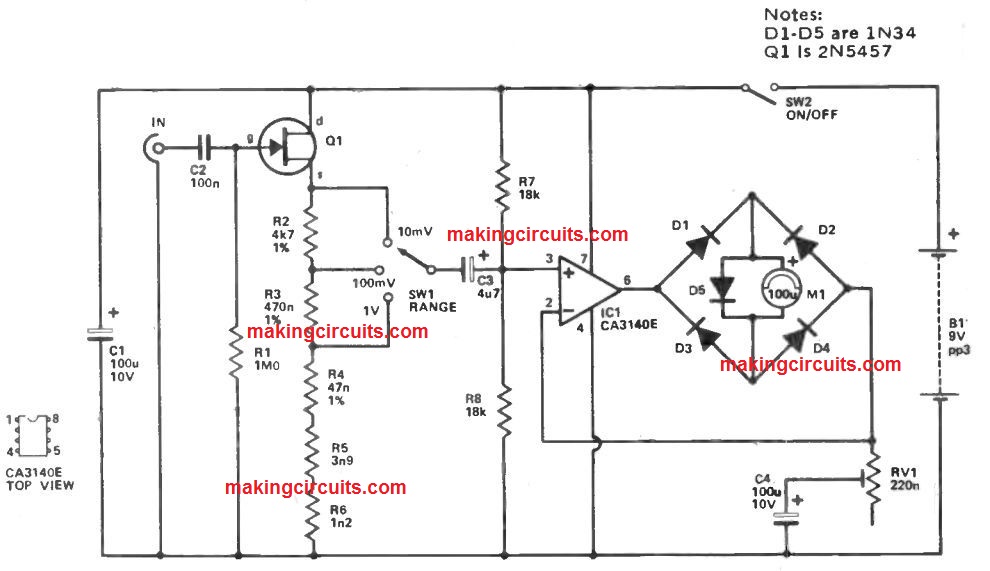
With low voltages placed on the rectifiers there is a high forward resistance, but this leads to little feedback and the amplifier possessing a high level of gain.
Hence small input signal amplitudes which may or else create no meter deflection because of the high rectifier resistance are increased until they provide the right meter reading.
As a result, even though rectifier is inherently non linear, it generates opposing non linear feedback which makes up with this and provides the unit linear scaling.
RV1 is employed to modify the circuit of the correct sensitivity and D5 safeguards the meter towards extreme overloads. Q1 is required like a low noise source follower buffer amplifier which provides the circuit a higher input impedance of around 1 Meg.
This particular makes sure that the piece of equipment imposes minor loading on the devices under test.
An attenuator is integrated at the output of the buffer stage, which could be utilized to slow up the standard 10 mV sensitivity to 100mV or 1V FSD.
The attenuator doesn't have any sort of frequency compensation as it is in a low impedance section of the circuit.
To adjust the unit it is turned to the 1V range, RV1 is placed at optimum resistance, along with a 1V RMS sound source attached to the input, RV1 is altered for full scale deflection of the meter.
The 1V audio source could be supplied by an AF signal generator fixed at the proper output level using a multimeter turned to a low AC volts range.
Milli-Voltmeter Circuit with Extended Range
A multimeter, since the name signifies, is a convenient testing tool, however it has its boundaries.
For instance, its range for measuring AC in the audio band is generally insufficient, as well as sensitivity, internal resistance and frequency reply of the cheaper moving-coil multi-purpose instrument usually results in a lot to be preferred.
The widerange millivoltmeter explained in this article shuts the gap in a really simple and easy way.
The instrument enables you to calculate alternating current of frequencies between 100 Hz and 500 kHz.
When utilizing MOS-FET input opamps the input impedance at all measurement ranges will certainly sum to 10 M .
At the lowest measuring voltage of 15 mV the level of sensitivity is certainly there is a full-scale deflection on the 100 p A meter.
Circuit Descriptions

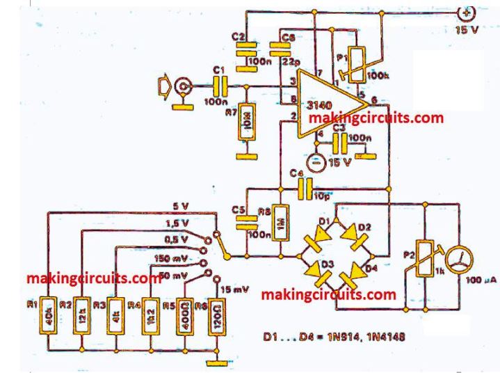
The opamp provides both as measurement amplifier and active rectifier.
The amount of amplfiication depends upon the switched resistors Rl to R6.
Together with the instrument set at a specific sensitivity range, the importance of a resistor can be discovered by simply separating the input voltage for a full deflection by 100 p A. When, for instance, at the measuring range of 150 mV, a 200 mV range is likely to be desired, resistor R4 ought to be converted to a value of 2 k.
Since the bridge rectifier diodes D1 to D4 are found in the feedback loop of the amplifier, generally there is compensation for the limit voltage of the diodes, for which purpose the mV scale reacts in a linear fashion.
The meter is zeroed using P1 and also the input short-circuited, even though the measuring range is determined oy P2.
The second option needs a calibration voltage which can be extracted from a small mains transformer having a secondary voltage of somewhat less than 5 V. At this level, the voltage can be treasured quite correctly using the multimeter.
The calibration voltage must then be connected to the extended range milli-voltmeter set at 5 V, and the reading of the 100 M A instrument is then adjusted, making use of P2, to the value of the calibration voltage.
Another measuring ranges are usually then set at the same time equivalent to the tolerance of the resistors R1 to R6.
Once the circuit is utilized to extend or supplement an existing multimeter, the moving-coil section of the multimeter ought to be used in the 100 M A range.
The best power supply to include in that situation is about 9 V, extracted from two small 9 V dry cells which will last quite a long time as the power intake is very low.