

A lot of model railway controllers possess the regrettable features of providing immediate starts and stops to the train which can make the model passengers nervous.
The model train controller circuit explained provides a constant acceleration or deceleration on speed variations, and also the speed and acceleration controls do not interact.


The power supply is 12V split through R8 and R9 so it seems to the op amps as a ± 6 V supply.
Voltages within this explanation are referenced to the 6V centre tap. IC1 and IC2 collectively work like a unity gain inverting amplifier, with the gain dependant upon R1 and R2.
The IC2's slope of output, depends upon Cl and R3 /RV2. The IC1 output may hence take up one of three states +6 V (hard positive), 0 V (balanced), -6 V (hard negative) determined by the output voltage happens to be more positive than equal to, or more negative compared to voltage fixed through RV1.
The output voltage may as a result ramp up or down at a regular rate until it is equal in magnitude (however opposite in sign) to the voltage on RV1 .
This really is summarized within the waveform drawing. Voltage b drives buffer amplifiers IC3 and IC4 to provide a push pull 1 2 V drive to the motor for forwards and reverse.
Remember that the feedback resistors R5 and R7 are obtained from the transistor emitters to compensate for the transistor V, drops.
The motor for this model train controller circuit needs to have some current cut out or limit linked in series with it to safeguard the transistors.
Being used RV1 fixes the speed, and RV2 the acceleration. Provides a really reasonable train control, even though a lot more ability is needed to halt a train precisely at a station platform.
To that end it is quite near to operating a real train.
Train Controller with Inertia and Brake
The working of this train controller circuit with inertia and brake can be understood with the following explanation.

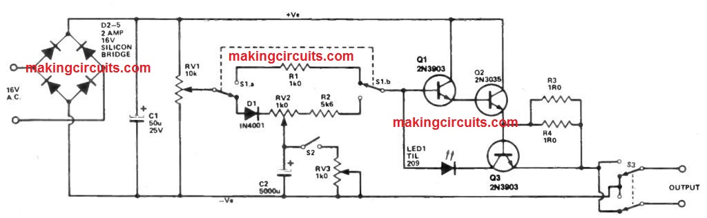
The diodes D2-5 provides full wave rectification the AC and C1 filters the output. RV1 operates as a regulator controlling train speed.
Switch S1 switches in the inertia simulator (including D1, RV1, R2 and C2). S2 switches in the brake, the action of which is modified through RV3.
RV2 regulates the level of inertia, in order that the train may take so long as ten seconds prior to even moving. Q1,2 work as a Darlington pair, providing current to the output.
Transistor Q3 tracks the output and supplies"short-circuit protection. Each time a short happens, LED 1 illuminates and also the current into Q1 is lowered. Therefore, the output is decreased.
A couple of 1W resistors are employed for R3,4 instead of a wirewound 1/2W resistor, which can be more expensive. S3 merely reverses the polarity and so the train.