

In this post we learn about a simple circuit which can be customized to generate a wide range of noise frequencies.
Noise refers to unwanted electrical signals in a pretty flat and wide frequency spectrum. A minimum noise factor is desired in the operation of most equipment and several measures are taken to reduce noise in the circuits.
But one instance where noise is useful is in checking circuit behavior for different inputs, like in microwave links, coaxial cables, CW (continuous wave radio telegraphy) and RTTY (radio teletype) decoders.
You can also use this circuit to produce actual noise sounds like the buzz of insects and winds.
How the Circuit Works

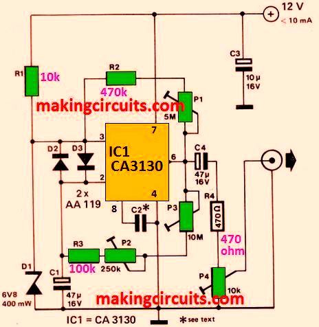
The main component of the circuit is IC1, a relaxation oscillator used. It is provided with positive feedback through P1-R2 and negative feedback by P3-P2-R3-C1. D1, a Zener diode, is the source of the noise.
P3 acts as the coarse modulator and P2 as the fine one in the amplification of the noise. P1 is used to set the noise bandwidth, with smaller effective values giving a narrow band and bigger values producing a wider band.
The negative feedback circuit allows the opamp to work as a low-pass filter - a low roll-off frequency results from a small feedback factor.
The C2 value also determines the pass band of the opamp - a value of 47uF would produce a buzzing sound of an insect. The D2 and D3 diodes act as input limiters while P4 is used to set the output level of the generator.
Current consumed by this noise generator circuit stays well under 10 mA at 12 V.