

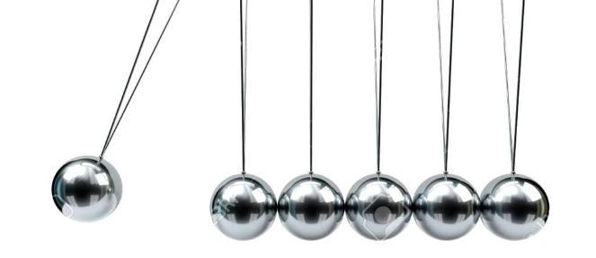
Many individuals have witnessed the desktop ornament/toy known as a ' Newton's cradle' (see figure 1), which includes generally five steel balls suspended in a row from a set of threads.


How the Circuit Works
When one of the end balls is raised and then released in order that it drops back and hits the following ball, the energy of the impact is transmitted through the other balls, with the effect that the ball on the opposite end of the row swings up.
It then in turn drops back, energy is again transmitted through the row, and the first ball swings up, and so on.
The energy losses of the system are relatively higher, and after numerous oscillations the balls are returned to rest.
The concept behind the circuit explained in this article, is to compensate for the natural energy losses of the system, in order that it continues to oscillate consistently.(i.e. until the circuit is disconnected or the batteries run out).
If, for the instant we ignore the energy losses, the frequency at which the system oscillates will be:
f = 1 / 2π (√ 1/g)
where 1 is the length of the thread and g is the force of gravity (9.81 m/s').
Thus with a length of 0.15 m, the essential frequency of the system will be somewhere around 1.3 Hz.
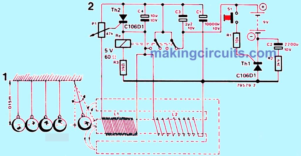
In order to compensate for natural energy losses, the magnetic field system shown in figure 2 has been developed.
Alongside the associated circuit, the concept is that a magnetic force is applied to one of the end balls in the cradle.
If the circuit is run by 6 1.5 V cells (manganese-alkali), the cradle should pursue to oscillate for around 5 days without disruption.
To set the circuit in operation, switch S1 should be pressed instantly prior to or after the end ball is set in motion, therefore triggering thyristor Th1 via resistor R1.
Capacitor C1 then charges up, as does C4. The moment a ball enters the field of the permanent magnet, a voltage is induced in coil L1, turning on thyristor Th2; the trigger point of the thyristor relies on P1.
The relay attached in the cathode of Th2 pulls in, so that current flows through coil L2, and an additional magnetic field is established which repels the ball.
As soon as the ball leaves the magnetic field, the voltage induced in L1 collapses and Th2 is switched off.
The procedure then repeats itself at the natural frequency of the system. If the ball is halted, no charge current will flow to C1, with the result that C2 will discharge.
If the discharge current is smaller than the holding current of Th1, the latter turns off and circuit switches off.
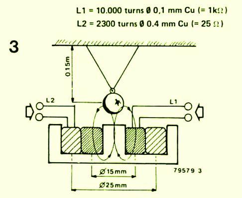
Figure 3 displays a cross-section of the coil and magnet system which is used in this newton's cradle circuit. L1 (10,000 turns of enamelled copper wire, 0.01 mm diameter, 1 k) and L2 (2300 turns enamelled copper wire, 0.4 mm diameter, 25 Ohms ) are wound on a permanent magnet core, and surrounded in transformer laminations.

Any easily accessible option form of thyristor works extremely well.