


This programmable electronic musical door bell circuit is really simple since the integrated circuit really does all the things! It should be stated that we now have created some substantial modifications to the application plan.
As shown in the below diagram the power supply is extracted from the 230 V mains: the TF1 secondary (2 x 9 V) with central tap is rectified by D1 and D2 (full-wave rectifier, ie rectifying the Two half waves), the middle connect becoming grounded; Once the polarity of the low voltage sinusoid (9 + 9 V) is positive max, D1 leads and D2 is obstructed; In the reverse situation (positive downwards), D1 is blocks and D2 leads. By way of the central tap towards ground, we now have at the terminals of C1 and C2 pulses Sinusoidal at 100 Hz that loads these to a consistent potential of approximately 11 V, that is adequate to operate the integrated circuit. This chip functions using its output stage (open collector) linked to a speaker (SPK) of 8 ohms impedance: the + of this speaker is attached to the positive power supply.
Take note the existence of capacitors in parallel: their functionality is always to clipping the level transitions of
In order that the small speaker reproduces smooth and enlightening tones (actually these capacitors permit a much more organic and accelerating damping of the tones).
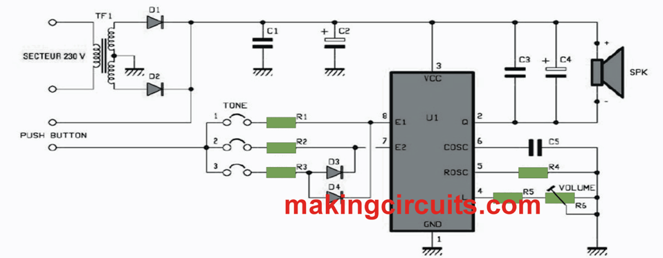
The exact level is effortlessly variable using the trimmer R6: with R5 it is the network for altering the current in the loudspeaker (the complicated resistance between pin 4 and ground is inversely proportionate
On the output level of the amplifier stage) and this is the reason why, while getting close to the cursor of R5, the tone level boosts and while it nears the ground it diminishes.
The SAE800 usually is at relaxation and eats a few μA: the speaker doesn't produce any audio. To audio may have a single or maybe more tones, push the bell switch attached by two wires to the PUSH BUTTON tips, in other words close the contact: the inner logic is activated and the very first tune is produced, after that probably , Based on the setting up of the jumpers, the 2nd and the 3rd.
Let's observe how to set the required audio, supposing the SAE800 is energized by high logic at around (5 V to the applied voltage pin 3) associated with one of many control pins (7 and 8); In case these pins are kept open or attached to ground, the integrated circuit is in "stand-by" function and utilizes practically
nothing. If E1 (pin 8) is sealed (jumper 1), it is in monotonic setting; With E2 (pin 7, jumper 2), the integrated circuit produces a two-note dissolved sequence (bitonal mode), the very first acute and the second the minimum; Ultimately, to change to the tri-tonal mode, pins 7 and 8 (jumper 3) should be established in the logic level. During the latter scenario, this is a diode array (D3 and D4) which, with jumper 3 sealed, provides the higher logic level and switches to the three-tone mode within a shifted diminishing sequence.
Without a doubt, when the jumper 1 is sealed, the positive voltage gets to straight the pin 8 and the solitary note is released after which diminishes steadily. Likewise, whenever jumper 2 is sealed: pin 7 reaches the high logic level and also the sequence of two shifted, dissolved and damping audio appears in the loudspeaker. Eventually, once the jumper 3 is closed, via D3 and D4 the control voltage gets to the lines E1 and E2 collectively: the diodes possess the functionality of polarizing two pins by making use of the voltage to a solitary line, that inhibits, if just one Is directly raised on, and the other is not. Without a doubt, when we use a polarity
Positive on jumper 3, both lead however, when we feed jumper 1 or jumper 2, these stay blocked simply because reverse polarized.
Concerning the activating of the IC in this programmable electronic door bell music circuit, remember that the lines E1 and E2 have a sort of anti-bounce: the logic triggers the functionality of the audio using a specific delay according to activation of the communicating input, Exactly, to prevent commutation unneeded and harmful to the correct working of the in this circuit, R4 and C5 have values decided to run the oscillator with a frequency of approximately 28.4 kHz, where the 3 notes are subsequently attracted: the very first is 1/20 of this frequency, ie 1.42 kHz, the second 1/6 more serious (1.19 kHz) and the 3rd 1/3 even a lot more significant (still compared to the first note), ie 940 Hz. The length of every tone is around 2.1 s. The audio reproduction in mono, bi or tri-tonal style comes to an end after 2.1 - 3.26 - 4.43 s correspondingly. Additionally, right after triggering and start of the reproduction of a series of tunes, the integrated circuit could be activated all over again just following a delay according to the parameterized mode: 2.1 s in mono, 3.26 in bi and 4.43 In tri-tonal.
You can now install the board in a plastic housing of appropriate size, as shown in the beginning of the article: the front panel will be pierced with regular holes for sound output from the loudspeaker and one of the short sides for The passage of the 230 V mains wires and those going to the doorbell button on the bearing. Place the chime against a wall, using dowels and screws, inside the house
(Choose the location so that you can always hear the ringing from anywhere in the house) and wire it.
PCB Design and Component Overlay for the electronic programmable musical door bell circuit

How to Test the electronic assembly:
Following a wide range of inspections, reestablish the 230 V mains and push the bell button: the loudspeaker must produce one, two or three tones. You might have closed riders 1, 2 or 3 (rememeber, just one at any given time). You are able to set
If possible the volume using the trimmer R6 and a tiny electric screwdriver. If absolutely no audio is released, examine with a multimeter whether the 230 V mains voltage gets to the terminal block or not. For additional assessments on the board, make sure to first switch off the mains supply (utilizing the circuit breaker in the table).
Technical Specifications and Features:
- Power supply input: 230 VAC
- Power consumption by the circuit: 3 VA
- Power output in the speaker: 1 W
- Push-button control
- Bell sound can be set to 1, 2, 3 tones in sequence
- Adjustable listening volume