


Making reference to the below drawn 12v motor current control schematics, the approach happens to be proper, in spite of this the circuit performance specifically in the second diagram seems to be wrong.
Let's investigate the diagrams one after the other:


The first diagram clarifies the fundamental current control stage calculations employing an opamp and a handful of passive elements, and it seems fantastic.
As suggested in the diagram as far as V1 - V2 is much less than 0.7V, the output of the opamp should really be zero, and the occasion it arrives above the 0.7V, the output should really drive high, however this might follow a PNP transistor at the output, not with an NPN,....anyway let's progress.
Here the 0.7V is with reference to the diode attached with one of the inputs of the opamp, as well as the thought is definitely to be sure that the voltage in this pin is more than the 0.7V limit in order that this pinout potential crosses the other complementing input pin of the opamp ending with a disconnect trigger to be drawn for the linked motor driver transistor (an NPN transistor as selected in the design)
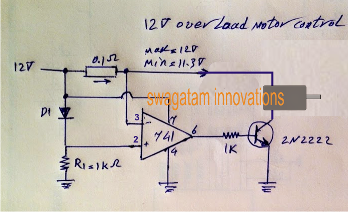
On the other hand in the second diagram, this disorder will likely not gain executed, in actual fact the circuit will never reply whatsoever, let's observe the reason why.
In the second diagram when power is activated, both the input pins attached across the 0.1 ohm resistor will likely be put through pretty much an equal level of voltage, but since the non-inverting pin has a dropping diode it will gain a potential which may be 0.7V cheaper than the inverting pin2 of the IC.
This would cause the (+) input acquiring a shade lower voltage than the (-) pin of the IC, which usually will generate a zero potential at pin6 of the IC right at the onset. With a zero volts at the output the attached NPN would probably merely refuse to begin as well as the motor will continue to be shut OFF.
With the motor shut off at this time there won't be virtually any current driven by the circuit and no potential change drawn across the sensing resistor. For that reason the circuit remains hidden with practically nothing taking place.
There may be a different problem in the second diagram, the motor in question will likely need to be attached across the collector as well as the positive of the transistor for producing the circuit efficient, here a relay lacks the role, and is as a result not preferred.
The damaged scenario talked about above could be reverted by means of swapping the contribution pinouts of the IC across the suggested issues, that is certainly across the sensing resistors, as presented in the sorted out third diagram.
Making reference to the third diagram whenever power is activated, pin2 will likely be put through a 0.7V significantly less potential than pin3 of the IC, forcing the output to go high at the onset.
With the output going high provokes the motor to commence and achieve energy, and in case the motor endeavors to attract a current more the the stipulated value, the exact amount potential impact will probably be released across the 0.1 ohm resistor, now because this potential starts growing pin3 starts off encountering a falling potential, just in case it collapses below the pin2 potential, the output will rapidly turn back to zero disrupting the base drive for the transistor and switching off the motor right away.
With the motor shut OFF in the course of that instant, the potential across the pins will certainly usually get normalized and will recover back to the original status, which will activate the motor and the scenario continue self-adjusting by way of a speedy ON/OFF of the driver transistor, keeping an appropriate current control over the motor.
The sensing resistor could be measured provided below:
R = 0.7/current
The following as described for a 0.7amp current limit for the motor the value of the current sensor resistor R needs to be
R = 0.7/0.7 = 1 ohm