

LOTS OF CIRCUITS for light dimmers have already been posted in the past which are usually of quite simple construction, and designed to use a rotary potentiometer.
Although these kinds of circuits are enough in many aspects - particularly in conditions of cost, there are several powerful factors behind a much more advanced dimming system.
The first objection to easy dimmers is that they most often have an unattractive knob through which light level is adjusted. A second objection could be that the light level can simply be adjusted through the position in which the dimmer is installed.
The push button dimmer circuit referred to in this project could be controlled from one or even more remote positions - e.g. doors on opposite sides of a room, top and bottom of a long flight of stairs, bedside tables - or even from a control point next to your armchair.
The unit comes with an ON/OFF switch and two (or more sets of push buttons, one of which in turn causes the light level to increase, easily from minimum to maximum in about three secs, and one which usually does the reverse.
The adjustment could be stopped at any specific level, and therefore level will probably be looked after without having change for periods up to 24 hours. The dimmer will certainly tackle incandescent or fluorescent lamps around 500 VA considering the particular heat sink yet, with a larger heat sink, can be employed around 1000 VA.
Wind the choke and transformer in compliance with the info presented in Tables 1 and 2. Be specifically cautious to deliver sufficient insulation amongst the primary and secondary of the pulse transformers.


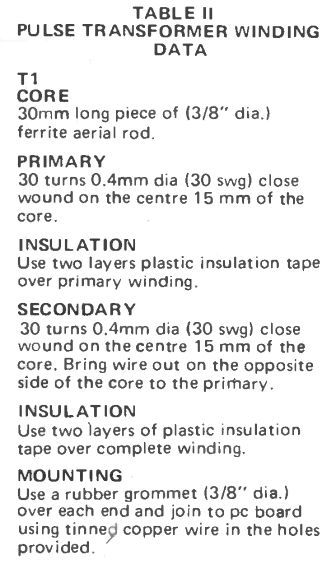
A small piece of aluminum (30 mm x 15 mm) bent at 900 in the centre of the long side, is utilized under the triac as a heatsink. The pulse transformer and also the choke are installed by way of rubber grommets and secured by tinned copper wire around the grommets and soldered into the holes given.
Almost all setting up, modifications needs to be made making use of plastic, or well protected tools. This push button dimmer circuit is live at line potential and for that reason risky to manage. BE EXTREMELY CAREFUL.
Potentiometer RV2 needs to be modified to choose the preferred minimum light level setting, (along with the down button held). Alter potentiometer RV1 for optimum light level (considering the up button placed) to be able to past the point where maximum light level is acquired.
In case the lamp load is fluorescent a lot more attention needs to be considered using these modifications. Furthermore the setting up should be redone if the fluorescent loading is changed. When adjusting the maximum light point on a fluorescent load, gradually enhance the light level till the lights just commence to flicker.
Then turn RV1 back right up until there exists simply a noticeable drop in light level. This increased setting trouble is because of the inductive nature of fluorescent loads. In case the needed minimum light level can't be acquired around the range of RV2, increasing R6 will give you lower light level range, and decreasing R6 provides a higher level range.
HOW IT WORKS
By using most advanced dimmers, we now have implemented a phase controlled triac for power control.
The triac, which can be considered to be a switch, is switched on with a pulse at a fixed point in every half cycle, and instantly turns off at the end of each half cycle.
Nearly all standard dimmers work with a basic RC and diac system to build the trigger pulse, but this specific dimmer is in effect voltage controlled.
The 120 volt ac is rectified by D1, D4. This full wave rectified waveform is clipped at 12 volts by R7 and ZD1. As no filtering is utilized, this voltage will certainly drop to zero throughout the last half millisecond of every half cycle.

To deliver the right timing, and also the energy needed to fire the triac, a programmable unijunction transistor (P.U.T.) Q3 is employed combined with capacitor C3.
A PUT in addition works similar to a switch within the subsequent way. When the anode (a) voltage is more than the anode -gate voltage (ag), the anode to cathode (k) path gets to be efficiently a short circuit.
The voltage on the anode -gate, is set through RV2 and, will be amongst 5 and 10 volts. Capacitor C3 is charged, by way of R6, and once the voltage around it surpasses that on terminal ag, the P.U.T. fires discharging C3 with the primary of pulse transformer T1.
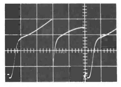
This induces a pulse in the secondary of T1 which gates on the triac. Since the voltage supply to R6 is unsmoothed the rise of voltage on capacitor C3 will abide by what exactly is known as cosine modified ramp. This provides a much more linear change in light level versus control voltage.
When C3 is released the P.U.T. might possibly remain on or switch off based on the individual device. If it turns off this could fire again if C3 charges swiftly enough, in spite of this the operation of the dimmer is not affected by either circumstance.
If C3 is not going to charge to the ag voltage prior to the end of the half cycle, the ag voltage will certainly fall at the end of the cycle and also the PUT will fire. It is really an crucial portion of the operation since it guarantees synchronization of the timing to the AC.
It is for this very motive that the 12 volt supply is not really filtered. To regulate the charge rate of C3 (and therefore the timing of the switch on of the triac within each half cycle) an auxiliary timing network of R5 and D6 is implemented.
As the value of R5 is a lot less than that of R6, C3 might charge much faster through this specific path. If we set the input of R5 at, say, 5 volts, the capacitor C3 might charge to around 4.5 volts easily and then at the slower rate arranged by R6.
This really is known as ramp and pedestal kind of charging. Due to the initial start provided by R5, the PUT might fire earlier, and the triac will switch on earlier, relieving much more power to the load. For this reason by controlling the voltage at the input of R5 we might control the output power. Capacitor C2 is employed as a memory device.
It could be released by R1 by using PB1 (up) or charged by R2 through PB2 (down). The capacitor C2 is linked through the positive side of the 12 volt supply and therefore once the capacitor is released the voltage in fact increases dependant upon the zero volt line.
Diode D5 is required to avoid the voltage increasing furthermore set by RV1. The capacitor C2 is attached to the input of Q2 by R3. Transistor Q2 is a field effect transistor FET that includes a quite high input impedance.
Therefore the input current is practically zero and the source tracks the gate voltage but at many volts level. (The exact voltage variation is determined by the individual FET). In case the gate voltage is changed, ie, the voltage on C2, the voltage placed on R5 will even differ.
By pressing either PB1 or PB2 the capacitor voltage and therefore the triac firing point and the power provided to the load might be different. Upon relieving the push buttons the capacitor will 'hold' this voltage - EVEN THOUGH THE POWER IS TURNED OFF - for prolonged duration's.
The memory time will depend on a number of aspects as outlined below:-
1. A capacitor with a leakage resistance is excess of 100,000 megohm is needed. Make use of a reliable capacitor, ideally rated at 200 volts. If at all possible attempt various brands.
2. The pushbutton switch needs to be rated for 120 Vac operation. This category possess greater separation and therefore insulation amongst the contacts. By physically disconnecting the pushbutton it is possible to find out whether this can be a reason for low memory times.
3. The FET on its own comes with a limited input resistance. We attempted several FETs without acquiring any kind of that could not really function. However usually do not neglect this chance.
The dimmer could be managed from numerous stations merely by paralleling sets of pushbuttons. No harm will certainly derive from pressing both up and down buttons simultaneously.
On the other hand including many stations enhances the chance of leakage and major loss of memory time. The dimmer needs to be installed in a dry dust free position as should the pushbutton.
Usually do not attempt to utilize the dimmer or pushbuttons in a bathroom or kitchen as moisture will leave the memory almost useless.
Circuit diagram of push button dimmer circuit.

