


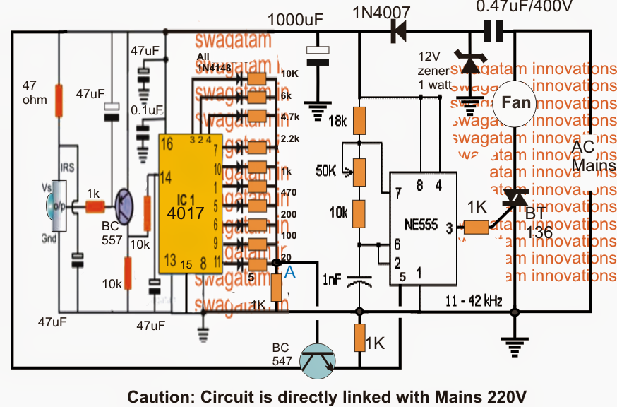

The article addresses an easy infrared controlled fan regulator or dimmer circuit employing common parts for instance a 4017 IC and a 555 IC.
Making reference to the proven remote controlled fan dimmer circuit, three main levels could be noticed incorporated: the infrared signal sensor stage applying the IC TSOP1738, the Johnson's decade counter, sequencer applying the IC 4017 and a PWM processor stage using the IC 555.
The a variety of functions associated within the circuit may be noticed by making use of the following points:
When an infrared beam concentrates at the sensor, the sensor delivers a low logic in accordance with this which usually leads to the PNP BC557 to carry out.
The sensor utilised here is a TSOP1738, you could read more about it in this particular simple IR remote control content
The conduction of the BC557 transistor in keeping with the IR beam links the positive supply to pin14 of the IC 4017 that may be considered to be a clock pulse by the IC.
This clock pulse is translated into a single sequential hop of a high logic from the current pinout to the next following pinout in the sequence across the presented outputs of the IC 4017.
This sequential transfer or shift of a high logic pulse from one pinout to the next across the complete outputs from pin#3 to pin#10 and back is completed in keeping with just about every short lived beam focused on the IR sensor by the IR remote handset.
You can easily discover the IC 4017 outputs gain a number of exactly measured resistors whose outer free ends are shorted and attached to ground via a 1K resistor.
The above configuration forms a resistive potential divider which yields a sequential incrementing or dropping potential levels at the node "A" according to the shifting of the high logics across the outputs as talked about in the above clarification.
This various potential is ended at the base of an NPN transistor whose emitter can be viewed attached to pin#5 of IC 555 that may be designed as a high frequency astable.
The 555 step fundamentally performs such as a PWM generator which may differ proportionately as its pin#5 potential is varied. The various PWMs are manufactured at its pin#3.
By default pin#5 is linked with a 1K resistor to ground which makes certain that if you have no voltage or minimum voltage at pin#5 causes an incredibly narrow PWMs at its pin#3 and as the potential or voltage at its pin#5 is raised the PWMs also achieve width consequently. The width is maximum when the potential at pin#5 reaches 2/3rd of the Vcc of its pin#4/8.
At this point it appears that, as the outputs from the IC 4017 shifts establishing a varied voltage at the base of the NPN, a respective amount of differing voltage is distributed over pin#5 of the IC 555 which usually is converted into an suitably changing PWMs across pin#3 of the IC.
Since the pin#3 of the IC is attached to the gate of a triac, the conduction of the triac is consequently inspired from high to low and vice versa in keeping with the modifying PWMs over its gate.
This is certainly successfully changed into a required speed control or an effective regulation of the associated fan across the triac's MT1 in addition to the AC mains input.
Consequently the speed of the fan evolves into adjustable from fast to slow and vice versa in accordance with the infrared IR beams toggled on the linked IR sensor of the circuit.
Tips on how to Install the circuit.
It could be carried out with the aid of the following actions:
In the beginning preserve the emitter of the BC547 transistor shut off with pin#5 of the IC555.
Now the two stages (IC 4017 and IC 555) could be realized to be isolated from each other.
First check the IC 555 stage in the following manner:
Disconnecting the 1K resistor across pin#5 and ground need to increase the speed of the fan to maximum, as well as connecting it back should drop it to minimum.
The above will demonstrate the appropriate performance of the IC 555 PWM stage. The 50k preset setting is not important and could be set to somewhere around center of the preset range.
Following, we should instead examine whether the IC 4017 output node at "A" generates a varying voltage from 1V to 10V in accordance with each pressing of the IR remote beam over the circuit's IR sensor.
If the above circumstance is achieved, it is possible to consider the stage to be performing appropriately, and now the emitter of the BC547 could be integrated with pin#5 of the IC555 for the final testing of the fan speed regulation using a IR remote handset.
The remote handset might end up being any TV remote control which we generally use in our homes.
If the above design is unable to perform effortlessly with a linked fan, it could really need to experience a minor alteration for bettering the benefits as presented below:
The circuit drives the help of a MOC3031 triac driver stage for enforcing a trouble free and clean fan control by way of the remote handset.
WARNING: THE WHOLE CIRCUIT IS DIRECTLY LINKED WITH THE MAINS AC, OBSERVE EXTREME CAUTION WHILE TESTING THE CIRCUIT IN POWERED POSITION