


For buildings that are big and tall where the water tanks are kept way up high over the terrace, keeping an eye on the water levels all the time by hand can be a real headache. It is not easy to keep track when the tank is sitting several floors above and then if the water overflows or dries out then that is another big trouble.
These days RF remote control modules have become dirt cheap and they can be a solid way to tackle this whole mess without running around checking the tank manually.
So why not take advantage of this? Let us dig into how we can put together a simple yet smart wireless water level controller circuit to make life easy. This whole idea came from a request by Mr. Jeff so let us get right into it!
Technical Specifications
Now here is my exact problem, I want to fix this circuit up for my home’s overhead tank. See I live on the first floor but the tank is all the way up on the fifth floor which means climbing up every time just to check water levels is out of the question.
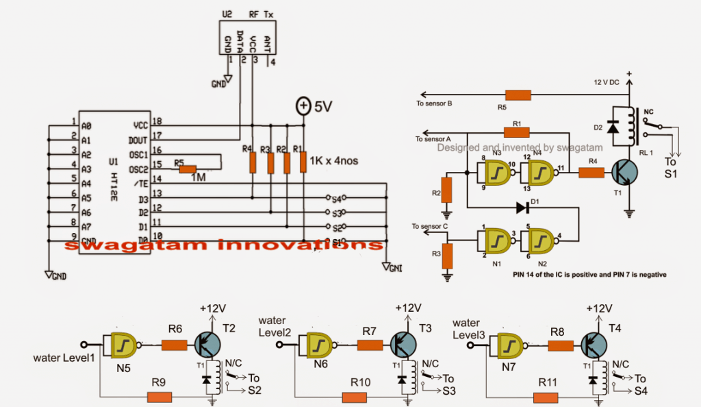
In the circuit shown above, there are push switches in the transmitter part. But instead of those push switches then if I place the D0 to D3 terminals inside the water tank then as the water level rises, one by one, D0, D1, D2, and D3 will touch the water and send signals straight to the receiver.
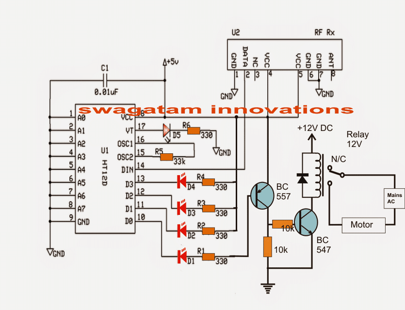
On the receiver side, the LEDs will light up step by step, showing exactly how full the tank is.
Now in the transmitter part, let us assume D0 represents the "tank empty" state. That means then if the tank is completely dry then none of the terminals will be touching the water so D0 will not send any signal.
Because of this, the LED at the D0 position on the receiver will stay off and in this condition, the motor should kick in and start filling the tank.
As the water starts rising eventually, then when D3 inside the transmitter touches the water then at this point, the corresponding LED at D3 on the receiver will turn on. Then when this happens then the motor should immediately stop, preventing overflow.
So now I need a circuit that does exactly this. Can you give me the right design for it?

The Working Design
The working of this circuit thing can be grasped in the way explained below:
So what we have done here is basically combined two totally separate sections. One of them is our automatic circuit for controlling the water level and the second one is a totally different circuit, which is for RF remote controlling purpose.
Utilizing Tx and Rx 433MHz RF Modules
This remote control thing consists of one Tx (which is transmitter) and one Rx (which is receiver). The way it works is, in the transmitter section, we have four different separate switches, and then these are pressed, they encode some data and fire off the signals straight into open air.
Now this receiver thing on the other side, it just snatches these signals out of thin air, makes sense of them by decoding the content and then hands it over to one of its four outputs depending on which particular data bit was sent over.
The output it selects does not just do nothing, no! It becomes HIGH but only for the time that the button on Tx side is being pressed down. The moment you release the button, then boom, the output goes LOW again.
Now the idea behind designing this water level controller that is based on this RF remote mechanism is very simple. We just need to arrange for the water level controller to operate the Tx buttons automatically, using relay contacts. These relay contacts get switched ON and OFF by the water level controller based on whatever water level it is detecting at the moment, all as per what the user has set it to do.
And then this whole idea has been properly implemented in the circuit that we are talking about here.
Understanding the Water Level Controller
Now if you see the diagram you will find some logic gates, namely N1 to N4, these are the ones that together make up the automatic water level controller circuit. What this section does is, then whenever the water level in the tank falls too low, to a certain set lower limit then the motor gets switched ON immediately. But then once the water rises all the way up to the top and fills up the tank completely then the motor is shut OFF automatically.
Before, the relay R1 used to be there for switching ON the motor and it worked by connecting its contacts directly to the motor and the AC mains.
But now, then for this particular setup that we are currently dealing with, we changed that! Now RL1 instead of controlling the motor, is simply wired to one of the Tx module’s switches (specifically, S1).
What This Means
So what is happening now? Now, then when RL1 gets activated, it directly causes pin10 of Tx module to start transmitting signals into the air. But then this activation only takes place then when the water tank is detected as completely empty.
And then when this transmission begins, the Rx module sitting somewhere far away receives those signals, understands what is up, and then activates its own relay which is attached to the appropriate output pin.
This relay that gets activated is the one that ultimately switches ON the remote pump motor that could be installed somewhere underground or at a high place, so that the required amount of water starts getting pumped up.
More Circuitry Involved
Then if you check the circuit diagram properly, you will also notice another set of logic gates—N5, N6, and N7. These ones are configured in a special way so that they work as NOT gates and their job is to keep checking and sensing the changing water levels inside the tank, then while the water is being pumped.
Now then as all this is going on, these gates keep performing their job, and then when they sense particular water levels, then they switch ON their respective relays which in turn close switches S2, S3, and S4. And then this action leads to the required transmission from Tx side to Rx side, indicating the current water levels.
And then what does the Rx do? It simply receives all these transmissions, decodes them accordingly, and then sends the information to its relevant output terminals.
One cool feature is that the receiver’s outputs are linked to LEDs and then these LEDs start glowing in a particular manner that helps the user understand how full the tank has gotten at any given time.
Why This Remote Feature Is Useful
Because of this remote-controlled function built into the water level controller, the owner of the system can now monitor and control a water tank that is located far away without having to manually check anything. It is a totally wireless, completely hassle-free experience.
The diagram below explains how the Rx section (the receiver) is wired up and then how it is made responsible for not just switching the pump motor ON and OFF but also for showing different water level indications in response to the signals sent from the Tx side.
Receiver Schematic

Parts List for the water level controller stage (N1----N4):
| Component(s) | Value / Specification |
|---|---|
| R1 | 100K |
| R2, R3 | 2M2 |
| R4 – R11 | 10K |
| T1 | BC547 |
| T2, T3, T4 | BC557 |
| D1, D2 | 1N4148 |
| All RELAYs | 12V, 400 OHMS, SPDT, contact amps as per load specs |
| N1 – N7 | IC 4093 (2 nos.) |
The output of the final unused gate (N8) may remain open, but the input must be terminated to either ground or (+).