

The basic principle applied to create burglar deterrent circuits the world over is to detect an unwarranted presence and ring an alarm or effect some kind of activity to alert nearby people.
But for that, the burglar has to first make sure nobody is home, presumably by getting no response on knocking or ringing the bell.
The alarm is activated only after they break in, but in most cases, the damage is done by then. But what if a system could be created that did not let it go that far in the first place?
Circuit Description
The circuit here is a good example. The ringing of the bell activates several monostables and, after an appropriate delay, turns on a suitable alarm or a pre-recorded programmed sound. This can be whatever you want, like the bark of a dog or even a voice saying something appropriate.


The burglar deterrent circuit is constructed using two monostables. P1 is used to set the time of delay between the bell being rung and the record being played, to any value between 0.22 and 2.4 seconds.
Whereas P2 is used to set the time for which the relay remains activated for the external alarm to sound. Thus can be between 47 seconds and 8 minutes 37 seconds. Relay contacts are used to turn the cassette player on.
The bell transformer is used to provide power to the circuit. The circuit, and so also the relay, is considered to be 6 V, consuming 50 mA of current.
Simple Burglar Alarm Circuit
A burglar alarm circuit can be extremely easy if non fundamental features for example entry and exit delays are disregarded, and this sort of a circuit is proven in this article.
It could be utilized in combination using commonly open (NO) or commonly closed (NC) contacts which may be the common door and window switches, trigger mats, and so on.
SCR 1 is a silicon governed switch (SCS) which can be an NPN/PNP built-in set of transistors linked to form an incredibly vulnerable thyristor.
Since burglar alarm circuit stands, R1 links the CK terminal to the negative supply and avoids SCR 1 from activating. The relay will never be energized plus the alarm is not going to sound.

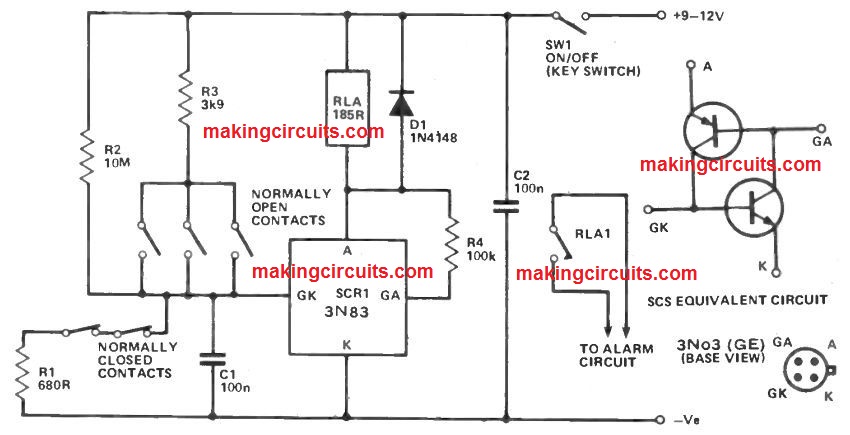
If more than one of the NC contacts need to open, SCR 1 will probably be turned on through the gate current it obtains via R2, because R1 can now be turned out of circuit.
Actually when the contacts have to shut again, SCR 1 will stay in the on state since it carries a built-in latching action.
Hence the relay will be triggered and its contacts link power to the alarm generator.
The burglar alarm circuit may also be activated by a more than one of the NO contacts closing, as R3 then offers an sufficient gate bias to switch on SCR 1.
When triggered the circuit can just only be reset by turning off making use of SW1.
The current via SCR 1 then drops to zero and also the latching action is overcome so the circuit is preparing to begin procedure yet again when SW1 is shut.
Even though just two sets of NC contacts are displayed, numerous contacts attached in series can be utilized.
Likewise, various NO contacts linked in parallel work extremely well. If no NC contacts are employed, R1 need to definitely be incorporated amongst the GK terminal of SCR 1 and also the negative supply rail.
C1, C2, and R4 are essential to avoid spurious process because of stray pick-up of noise spikes or noise pulses within the supply lines.
D1 is a protection diode which usually eliminates the high back EMF created along the relay coil as it de energises.
The standby current usage of the unit is just about 1uA therefore, the unit could monetarily work through normal dry cell batteries in case preferred.