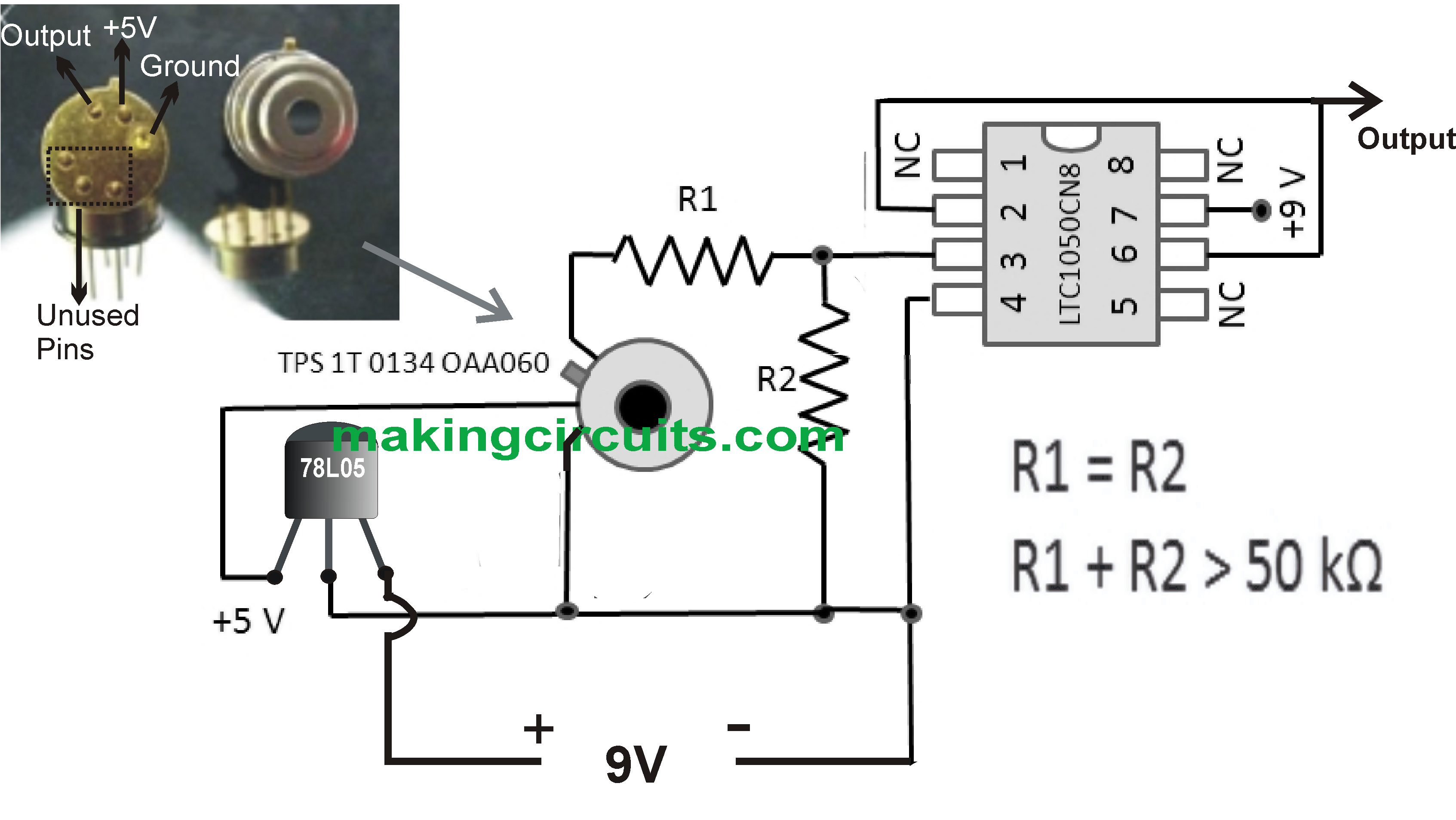
A simple infrared thermopile sensor circuit diagram is shown underneath. The op amp must be a excellent low-noise unit.
We usually make use of the LTC1050 for such purposes, however various other pin-compatible selections may be present and tried.
(The all-pervasive 741 op amp is not going to be eligible as a "low-noise" substitute, although it is pin-compatible.)
Since this is undoubtedly a low-power circuit, A 78L05, 5V regulator inside a TO-092 casing may be the suitable preference.
The pins on the thermopile sensor A2TPMI are vulnerable, and yes it may very well be a smart idea to connect a minimum of one of the unused pins to an isolated solder pad for mechanical steadiness.
Just about all parts in the diagram are as looked at from "top," meaning through the component angle of a PCB.
Determined by how this simple infrared thermopile sensor circuit is encased to safeguard it from weather condition, it may be recommended to flip the A2TPMI over and attach this within the reverse section of the PCB. If you carry out this, ensure you hook up the relevant pinouts accordingly!