

You can build this simple PWM controlled pulse generator circuit with the help of a single inverter gate, which may be in the form of a single gate from the IC 4093 with its input pins shorted together, or simply a NOT gate.
How the Circuit Works
Any one of the total four gates can be used to produce an oscillator with a variable duty-cycle and a set frequency. The RC time-constant of this network that has a capacitor C1 and resistor R1+P1 helps in determining the pulse duration.

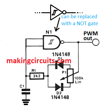
A perfectly symmetrical square wave signal is obtained at output when the wiper of this potentiometer is adjusted in the mid-position. In any case, when the position of the P1 is altered, the C1 takes a different time to discharge.
Due to this, sooner or later, gate N1 gets triggered and results in either positive or negative-going. This concludes to the fact that the pulse width varies.
R1 acts as a protective measure in case the P1 is at minimum resistance. This means that the duty-cycle is not 100% variable but a 98% range is perfectly acceptable.
Variable Oscillator Pulse
The value of the capacitor C1 also determines the frequency of the oscillator as the sum of RC-time constant is the same for both. Often times, several different frequencies are required, a multi-way switch with a corresponding number of capacitors can be included to replace C1 (refer figure below). This lets the pulse duration to be different in corresponding steps from the switch.

