

This beneficial solar Ni-Cd circuit functions to prevent overcharging of batteries compared to conventional charger circuits which are ordinarily built by employing only one Schottky diode and a solar panel.
Compact sized solar cells can be purchased at much lower prices or you can dismantle the old solar powered garden lamp and get them out. Throw in a few electronic components, you could build yourself a homemade charger capable of charging a set of Ni-Cad batteries.
Operation
The simplicity of the NiCad solar charger circuit is defined with the number of components used. With only two transistors and several passive components, you’re good to go.
The voltage across the batteries is constantly observed and when it crosses more than a specific level, a power resistor is forced to connect in parallel with the solar panel.
As a result, the panel’s output voltage drops and halts further charging of the batteries. In simpler words, this means the batteries are fully charged.

How the Circuit Works
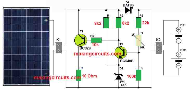
The circuit around T2 monitors the voltage while the Zener diode D2 shifts the emitter voltage of T2 around 1.4 V.
The base voltage to T2 is provided by potential divider R3, P1 and R6. When this voltage elevates more than 2 Volts (1.4 V plus T2’s base-emitter drop), the transistor conducts.
At this time, the base of T1 is pulled lower through resistor R5 which also forces T1 to conduct.
Power resistor R7 averts the current from the solar panel which allows its voltage to drop, stopping the batteries from being charged. We recommend using a 10 Ω, 1 W resistor as it is more than enough.
Based on T2 and D2, the components of the potential divider, you have to play around with preset P1 to get the precise final voltage for the NiCd batteries.
The typical value for a fully charged battery is about 1.44 V. In this circuit setup where two batteries are connected in series, some adjustments need to be made so that T2 begins conducting when the voltage across K2 achieves 2.88 V.
We hear from you. In case you need to charge more than two batteries simultaneously, you must alter the potential divider.
That is simple as you just need to increase R3’s value which immediately allows the charger circuit to work with three or four batteries. Remember to connect them in series, though.
How to Build
Building this circuit is pretty straightforward and can be done even on a protoboard. Things become easier when connecting the leads from the solar panels and the batteries to the board if you use screw terminals for the input and output connectors.
The number of cells that need to be charged dictates the minimum voltage of the solar module. Normally, voltage drops range from 0.3 to 0.4 V across Schottky diode D1.
Therefore, the nominal module voltage must be more than the charge voltage determined by P1 by around 0.3 to 0.4 V.
A standard solar module, sometimes called as an array that can charge a pair of cells, comprises 8 series-connected solar cells.
Given adequate sunlight, this type of module supplies around 140 mA at 8 times of 0.45 V, which is 3.6 V. It is obvious you can opt for larger modules with a higher current rating to reduce charger time, but it is costly.
A completely flat 1400 mAh battery pack will need somewhere around 12 to 14 hours of uninterrupted sunshine to fully charge using the 140 mA.
We strongly advise observing the following when you’re constructing the circuit. The usual structure of a Zener diode rated at 1.4 V houses two normal diodes connected in series.
This mock-Zener must be connected in forward bias and not in reverse-biased position like an actual Zener. What we mean is to ensure the cathode (the connection with the ring) is attached to the ground.
How to Set Up
When regulating the final charging voltage for this solar Ni-Cd charger circuit, it’d be best if you could momentarily replace the batteries with an adjustable DC power supply. Fundamentally, the output is configured to 2.88 V.
Next, connect a voltmeter across power resistor R7. Place the solar panel where the sun shines the brightest and set the preset to the maximum resistance.
Now, gently reverse the dial until the voltmeter catches a few volts, showing that T1 is conducting. That is it. You’re done with the adjustment and can swap the batteries back in place of the power supply.