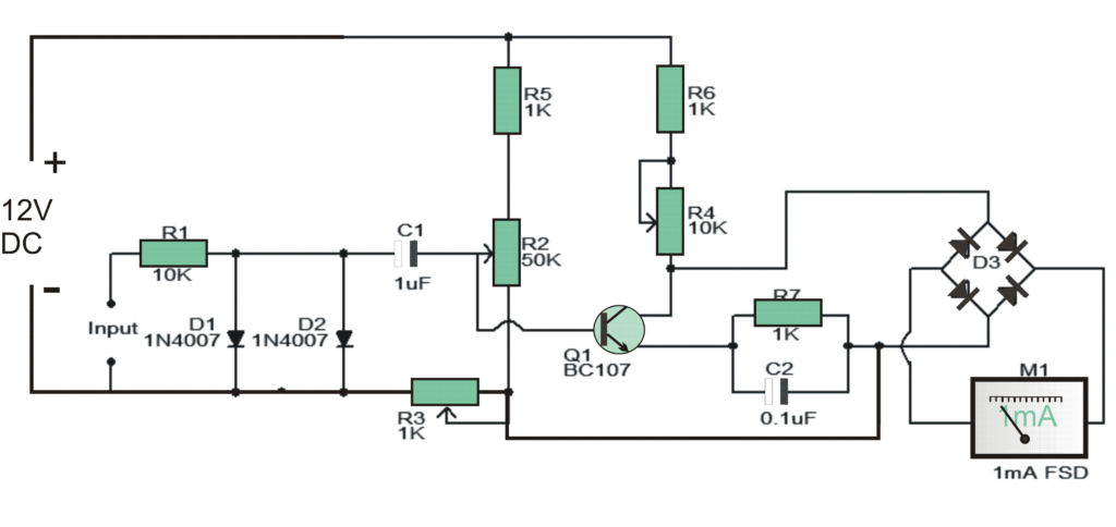
This circuit can be used like a tachometer for measuring the speed of vehicle engine by converting its ignition pulses into linear analogue voltage output.
Here is a straightforward circuit that can be utilized as a tachometer.
The circuit is fundamentally a recurrence to current converter which changes over the approaching sign into a relative current to drive the meter.
The avoidance on the ammeter will be corresponding to the recurrence of the approaching sign. For utilizing this circuit as an auto tachometer, the info terminal An ought to be joined with the flash fitting link and terminal B ought to be associated with the vehicles ground.
How the Circuit Works
For adjusting the circuit, set R2 at 25K and R4 at 5K. Power up the circuit and food the info terminal with a 60Hz square wave frame your capacity generator.
Alter R2 so that the meter demonstrates 0.36 Mama (equivalent to 3600rpm).
Presently detach the information flag and conform R3 so that the meter demonstrates 0mA.Now unite the 60Hz sign again and if the meter does not demonstrate 0.36mA alter R4.A totally balanced circuit will demonstrate 0mA at 0Hz and 0.36mA at 60Hz.
Notes.
- The circuit can be assembled on a Vero board.
- I have not tried this circuit on any vehicles. So utilize this circuit on your vehicles at your own particular obligation.
- In any case, the test utilizing the signs from my capacity generator was satisfactory.
- The ignition voltage from the sparkle plug terminal is in the Kilo volts.
- The motor must be OFF while making associations and you must be exceptionally cautious to maintain a strategic distance from stun perils.
- Attempt this circuit on your vehicles just on the off chance that you have adequate knowledge and experience on car electricals.
- I have no obligation on any disaster.
- The circuit can be powered from 12V DC.
- The extension D3 can be made utilizing four 1N4007 diodes.
- M1 can be a 1mA FSD ammeter.
