• Skip to main content
  • Skip to primary sidebar

Making Easy Circuits

Learn and build electronic circuits

You are here: Home / Signal Processor / Simple Tachometer Circuit

Simple Tachometer Circuit

Last Updated on September 22, 2021 by Admin 1 Comment

This circuit can be used like a tachometer for measuring the speed of vehicle engine by converting its ignition pulses into linear analogue voltage output.

Here is a straightforward circuit that can be utilized as a tachometer.

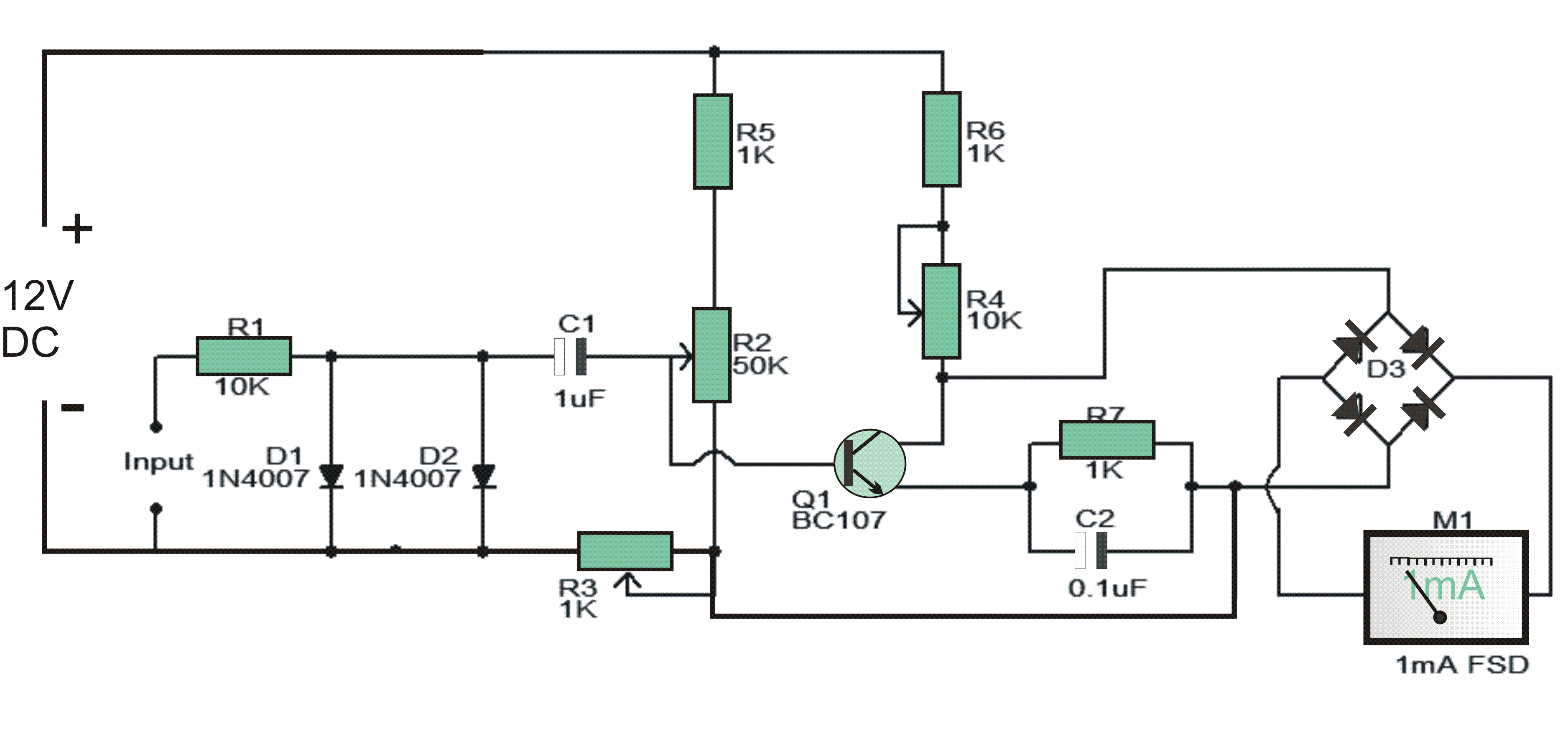
The circuit is fundamentally a recurrence to current converter which changes over the approaching sign into a relative current to drive the meter.

The avoidance on the ammeter will be corresponding to the recurrence of the approaching sign. For utilizing this circuit as an auto tachometer, the info terminal An ought to be joined with the flash fitting link and terminal B ought to be associated with the vehicles ground.

How the Circuit Works

For adjusting the circuit, set R2 at 25K and R4 at 5K. Power up the circuit and food the info terminal with a 60Hz square wave frame your capacity generator.

Alter R2 so that the meter demonstrates 0.36 Mama (equivalent to 3600rpm).

Presently detach the information flag and conform R3 so that the meter demonstrates 0mA.Now unite the 60Hz sign again and if the meter does not demonstrate 0.36mA alter R4.A totally balanced circuit will demonstrate 0mA at 0Hz and 0.36mA at 60Hz.

Notes.

  • The circuit can be assembled on a Vero board.
  • I have not tried this circuit on any vehicles. So utilize this circuit on your vehicles at your own particular obligation.
  • In any case, the test utilizing the signs from my capacity generator was satisfactory.
  • The ignition voltage from the sparkle plug terminal is in the Kilo volts.
  • The motor must be OFF while making associations and you must be exceptionally cautious to maintain a strategic distance from stun perils.
  • Attempt this circuit on your vehicles just on the off chance that you have adequate knowledge and experience on car electricals.
  • I have no obligation on any disaster.
  • The circuit can be powered from 12V DC.
  • The extension D3 can be made utilizing four 1N4007 diodes.
  • M1 can be a 1mA FSD ammeter.
tachometer circuit

You'll also like:

  • 1.  3 Phase Signal Generator Circuit
  • 2.  Sine wave Generator Circuit using Wein Bridge Oscillator
  • 3.  Dog Barking Sound Simulator Circuit
  • 4.  Simple Sawtooth Generator Circuit
  • 5.  Simple Voltage Controlled Oscillator using IC 555
  • 6.  RC Passive and Active Filters Explained

About Admin

Hey friends, Thanks a bunch for stopping by this site! I am an engineer with a Bachelor of Engineering in Electronics and Telecommunication. One of my passions is gathering information from all sorts of electronics books and tutorials. I then take that information and compile it into a language that is super easy to understand. My goal is to make those complex electronics circuit concepts and technical terms much more accessible for all the new and budding electronics engineers out there. I can also design customized circuit diagrams as required by the users.
If you have any questions related to this field, please do not hesitate to drop a comment! I am always here and ready to help you out with any queries you might have. I cannot wait to hear from you!

Reader Interactions

Comments

  1. Mahyar says

    May 29, 2023 at 8:43 pm

    Hello
    This is not a good design, with two transistors, the number of parts, especially potentiometers, can be reduced and we can achieve much better accuracy.

    Reply

Leave a Reply Cancel reply

Your email address will not be published. Required fields are marked *

Primary Sidebar

Categories

  • 3 Phase (4)
  • 8051 Microcontroller (1)
  • Arduino (11)
  • Audio and Amplifier (102)
  • Automation (8)
  • Battery Chargers (64)
  • Bicycle Projects (4)
  • Car and Motorcycle Projects (39)
  • Datasheets (10)
  • DIY Projects (5)
  • Electrical (15)
  • Free Energy (6)
  • Games Projects (2)
  • High Voltage (14)
  • Hobby Projects (30)
  • Household Circuits (2)
  • IC 555 Circuits (5)
  • Ignition Circuits (2)
  • Indicators (50)
  • Infrared (6)
  • Inverter Circuits (29)
  • Lights and Lamps (97)
  • Medical (8)
  • Meter and Tester Circuits (38)
  • Motor Driver (17)
  • New Circuits (56)
  • Oscillators (30)
  • Pets and Pests (5)
  • Power supply (80)
  • Protection Circuits (25)
  • PWM (9)
  • Remote Control (20)
  • Security and Alarm Circuit (48)
  • Sensors and Detectors (66)
  • Signal Processor (23)
  • Solar Controller Circuits (62)
  • SSR (3)
  • Temperature Controller (20)
  • Timer (25)
  • Transformerless (7)
  • Transmitters (12)
  • Tutorials (45)
  • UPS (2)
  • Voltage Regulators (57)
  • Water Sensor and Controller (29)
  • Home
  • Privacy Policy
  • Contact
  • Disclaimer
  • Copyright

© 2025 · Making Easy Circuits