


This specific circuit has been made with Win bond’s ISD1616 IC (SMD) IC, that is certainly a purely integrated, single-chip, single message voice record and playback system essentially matched to a variety of consumer electronics products. Messages are saved in flash memories manufactured in exclusive Multilevel Storage Technology (MLS).
As a result, voice or audio data are saved straight to the memory space in their organic form with virtually no compressions as done in digital technique, offering top quality, solid-state audio duplication.
The circuit offers excellent audio recording using straightforward procedures. Message length is consumer selectable in ranges from 10 to 20 Seconds based on the sampling rates from 4 KHz to 12 KHz variable through on board potentiometer (preset), presenting you increased versatility in timeframe versus recording quality.
Message recording and playback is not hard applying on board tact switches. This design works extremely well in number of application like, Interactive Games and booths, Light and sound shows, video gaming devices, educational baby toys, robots, animatronics, lifts/escalators, warning devices, security alarm systems, audio guide, appliances for the home.
The circuit operates on 5V DC @ 100mA. It utilizes nominal current in standby function normally 1uA to 100ua (With no power LED). The unit gets into into standby setting automatically as soon as a recording or a playback operation is accomplished for power saving reasons.
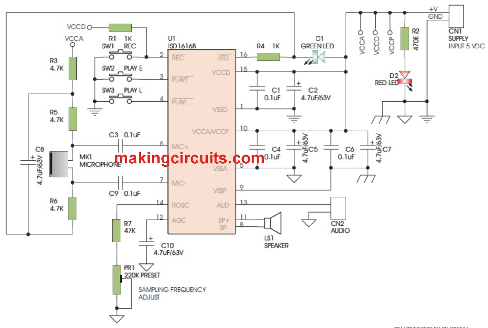
Circuit Schematic

Applications
- Toys and games
- Entertainment Products
- Interactive Video games
- Lifts/Escalators
- Warning Devices
- Burglar alarms
- Music Instruction
- Kitchen appliances
- Robotics
- Animatronics
- Light and Sound Show
Specifications
- Specified Power supply input is 5 VDC @ 100 mA
- Power supply can be within 2.4 to 5.5 VDC
- Standby current is around 1 uA and 10 uA maximum with no power LED
- IC normally gets into a standby mode right after a record playback cycle is accomplished
- Microphone preamplifier with automatic gain control built in IC
- PWM Class D speaker driver
- Is able to Drive a 8 Ohm speaker directly or even a buzzer
- AUD current output for operating external power device
- On-board microphone
- Simple functions via microswitches switches
- Integrated tact switches for Level trigger Play, Edge trigger Play, and Recording
- Integrated power indication
- Integrated preset for sampling rates settings
- Integrated recording indication
- Low Noise excellent quality voice record/playback
- Approximate massage retention time is 100 years
- Number of Record cycles is around 1 lac times
- Speaker is not provided with kit
How to Test the Circuit,
Hook up the 8 ohms 0.5W speaker to LS1 (SPK), implement 5V DC to CN1, and ensure polarity is proper or else it could destroy the IC. CN2 (AUD) is current drive output for connecting the circuit with additional audio amplifier.
How to Record A Message
The unit starts off recording anytime REC switch is pressed or recording pin of IC drawn HIGH to LOW and continues at LOW. Recording ceases as soon as the recording button removed or the signal on ICs pin comes back to HIGH. The unit begins recording right from the start from the memory as soon as REC transits through HIGH to LOW and continues at LOW. A record cycle is carried out when REC is drawn to HIGH or complete memory is loaded up. After that an End-of-Message (EOM) marker is composed at the finish of message, which allows a succeeding Playback cycle to generate effectively. Therefore, the unit automatically makes its way into into standby setting. REC normally takes priority over any playback functions. In case REC is drawn LOW within a playback cycle, the playback right away puts a stop to and recording begins right from the start of the memory. The REC pin comes with an internal pull-up feature.
How to Play the recorded message
Edge-trigger Playback: A playback functioning begins as soon as switch (SW2) PLAYE is clicked or PLAYE pin of IC finds a LOW going potential going above the selected debounced period
Level-trigger Playback: A playback functioning commences whenever switch (SW3) PLAYL is activated and playback halts whenever switch is released. PLAYL pin of the IC picks up a LOW going potenial and continues to be at LOW. Playback ceases once the signal reverts to HIGH
Time-frame
The ISD1616 IC delivers record/playback length from 10.6 seconds to 32 seconds. Sampling rate and time-span are decided by on board 220K Ohms PR1 potentiometer hooked up to the Rosc pin.
| Sample Rate | Rosc. PR1 Potentiometer | Duration |
| 12Khz | 60K Ohms | 10.6 Seconds |
| 8Khz | 80K Ohms | 16 Seconds |
| 6.4Khz | 100K Ohms | 20 Seconds |
| 5.3Khz | 120K Ohms | 24 Seconds |
| 4Khz | 160K Ohms | 32 Seconds |
D1 (Green LED)
The D1 Green LED turns ON while the recording is being done, the output pin of IC allows an active-LOW signal while the recording operation is ON, which permits turning on a D1 (Green LED) indicating “record-in-progress” status. However, while the playback process is ON, the D1 LED will show a blinking illumination for a few number of times per second indicating a “playback-in-progress” operation. This will go back to an OFF state when the recording or the playback operation are over.
D2 (RED LED)
D2 simply works like a power switch ON indicator, it will be in the illuminated state as long as power is on.
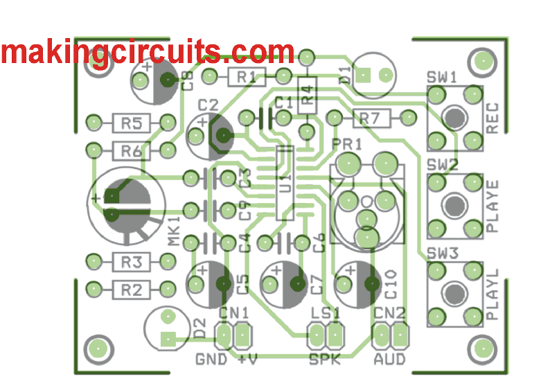
PCB Layout
