


A voltage stabilizer is a device which can be used to detect unsuitable voltage levels and rectify them to deliver a fairly steady output at the output where the load is connected.
Right here we are going to examine the design of an easy automatic mains AC voltage stabilizer which might be utilized for the above function.
How the Circuit Works
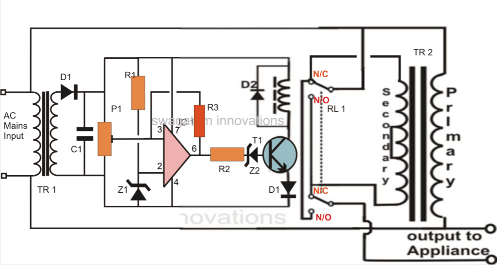
Talking about the figure we come across that the entire circuit is set up with the single op amp IC 741. It becomes the control section of the whole design.
The IC is wired as a comparator, everyone knows how well this mode suits the IC 741 and other op amps. It's two inputs are appropriately rigged for the stated procedures.
Pin #2 of the IC is clamped to a reference level, produced by the resistor R1 and the zener diode, while pin #3 is utilized with the sample voltage from the transformer or the supply source. This voltage evolves into the sensing voltage for the IC and is instantly proportional to the varying AC input of our mains supply.
The preset is employed to set the activating point or the threshold point at which the voltage might be believed to be harmful or improper. We are going to talk about this in the establishing process section.
The pin #6 which is the output of the IC, goes high the moment pin #3 gets to the set point and triggers the transistor/relay phase.
In the event the the mains voltage exceeds a specific threshold, the ICs non inverting identifies it and its output instantly goes high, activating the transistor and the relay for the required activities.
The relay, which is a DPDT type of relay, has its contacts wired up to a transformer, which can be a normal transformer improved to carry out the function of a stabilizer transformer.
It’s primary and secondary windings are correlated in such a manner that by means of suitable switching of its taps, the transformer has the capacity to add or deduct a particular magnitude of AC mains voltage and generate the subsequent to the output linked load.
The relay contacts are correctly incorporated to the transformer taps for performing the above actions as per the commands given by the op amp output.
So if the input AC voltage has a tendency to boost a set threshold value, the transformer deducts some voltage and tries to quit the voltage from achieving harmful levels and vice versa during low voltage circumstances.
220V voltage stabilizer circuit diagram


Parts List for the SIMPLE AUTOMATIC VOLTAGE STABILIZER CIRCUIT DIAGRAM
- You will require the following components to make this homemade automatic mains voltage stabilizer circuit:
- R1, R2 = 10K,
- R3 = 470K,
- P1 = 10K preset
- C1 = 1000 uF / 25 V
- D1, D2 = 1N4007,
- T1 = BC547,
- TR1 = 0 - 12 V, 500 mA,
- TR2 = 9 - 0 - 9 V, 5 Amp,
- IC1 = 741,
- Z1, Z2 = 4.7V/400mW
- Relay = DPDT, 12 V, 200 or more Ohms,
Approximate Voltage Outputs for the Given Inputs
INPUT------OUTPUT
200V -------- 212V
210V -------- 222V
220V -------- 232V
225V -------- 237V
230V -------- 218V
240V -------- 228V
250V -------- 238V
How to Set Up the Circuit
The suggested easy automatic voltage stabilizer circuit might be set up with the following procedures:
In the beginning do not hook up the transformers to the circuit.
Making use of a adjustable power supply, power the circuit across C1, the positive goes to the terminal of R1 while the negative goes to the line of D2’s cathode.
Set the voltage to about 12.5 voltage and adjust the preset so that the output of the IC just becomes high and causes the relay.
Now decreasing the voltage to about 12 volts should make the op amp trip the relay to its original state or make it de-energized.
Repeat and verify the relay action by modifying the voltage from 12 to 13 volts, which could produce the relay flip flop respectively.
Your starting process has ended.
Now you might hook up both the transformer to its suitable positions with the circuit.
Your simple home made mains voltage stabilizer circuit is ready.
When set up, the relay trips at any time the input voltage exceeds 230 volts, bringing the output to 218 volts and keeps this distance constantly as the voltage extends to higher levels.
When the voltage falls back to 225, the relay gets de-energized pulling the voltage to 238 volts and keeps the impact as the voltage further goes down.
The above activity keeps the output to the appliance well between 200 to 250 volts with fluctuations starting from 180 to 265 volts.