The post narrates a simple yet accurate sine wave generator circuit using a typical Wein bridge oscillator
A Wien bridge oscillator is actually a form of electronic oscillator which builds sine waves. It could possibly produce a wide variety of frequencies. The oscillator is dependent on a bridge circuit formerly formulated by Max Wien in 1891 for recording of impedances. The bridge consists of 4 resistors and two capacitors. The oscillator could additionally be seen as a positive gain amplifier merged with a bandpass filter that delivers positive feedback. Automatic gain control, deliberate non-linearity and casual non-linearity restrict the output amplitude in a variety of executions of the oscillator.

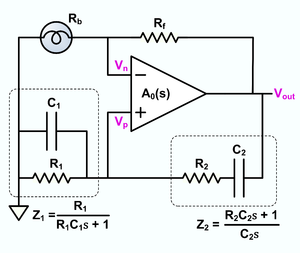
The circuit displayed above represents a typical setup of the oscillator, using automated gain control, applying contemporary parts. Based on the situation that R1=R2=R and C1=C2=C, the frequency of oscillation is offered by:

along with the affliction of steady oscillation is assigned by


A sine wave generator circuit using a Wien bridge oscillator may be designed adjustable by making use of two frequency rendering components which can be altered concurrently at substantial tracking precision.
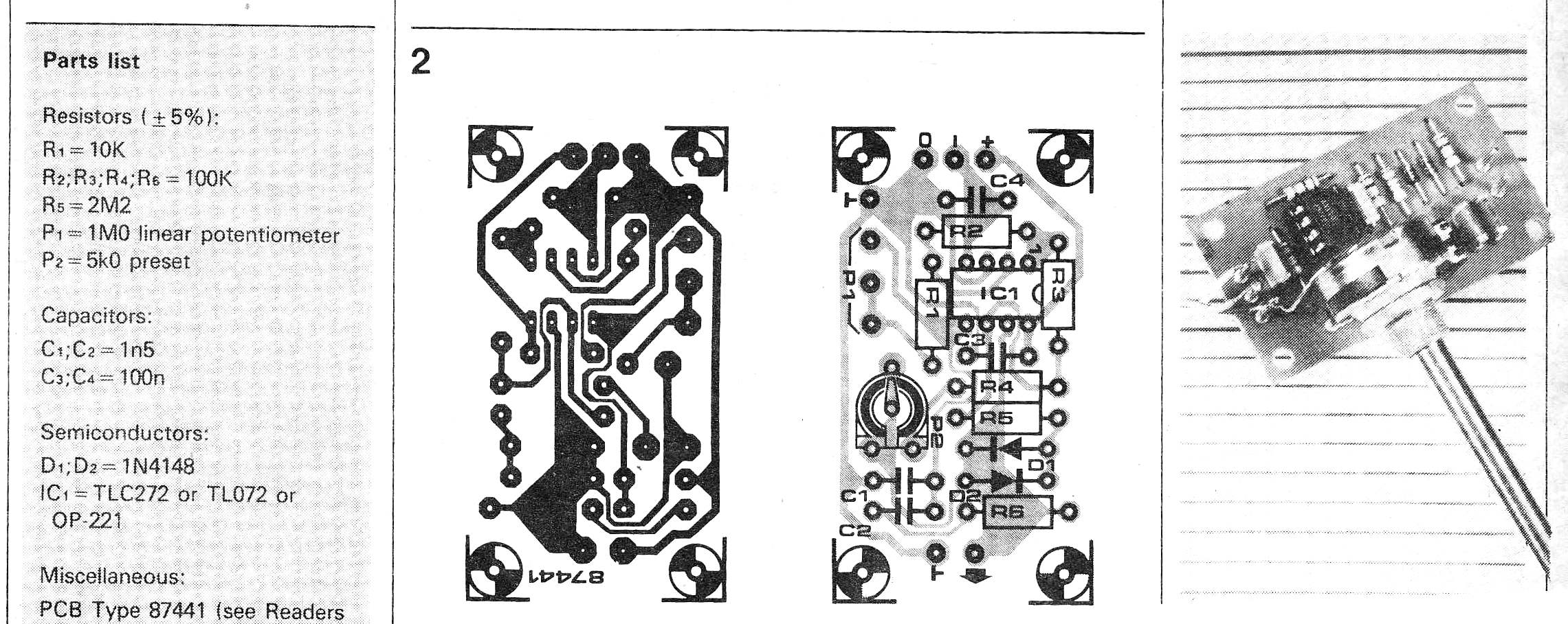
Excellent tracking pots or adjustable capacitors tend to be, however, costly and hard to acquire. In order to refrain from needing to utilize this type of component, this oscillator was created to work using a single potentiometer.
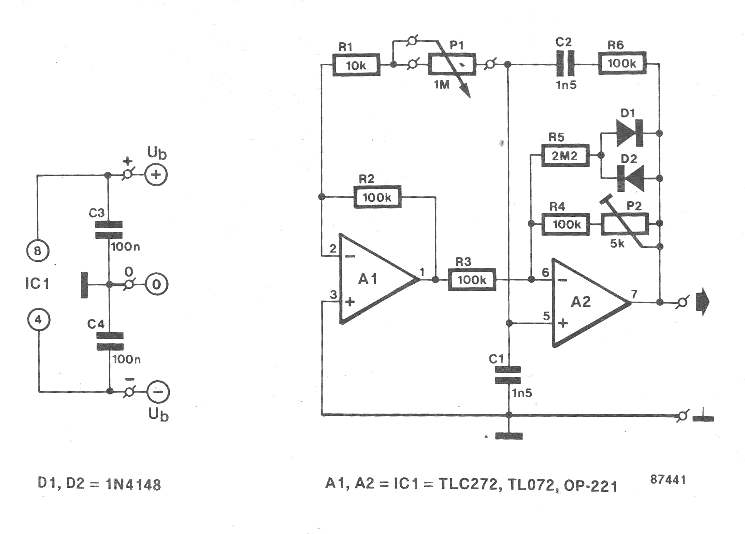
The output frequency, fo, will be determined via fo = 1/(2 x pi x RC x root x alpha) wherein R=Rz=R¤=R4=R6, C=C1=C2, and alpha=(P1+R1)R.
Preset P2 makes it possible for modifying the all round amplification in a way that the output signal includes a realistically steady amplitude (3.5 Vpp max.) within the complete frequency range.
The expressed elements enable the frequency to be altered throughout 350 Hz and 3.5 kHz. Additional frequency ranges will be conveniently described using the above mentioned expression, eventhough it must be observed that the higher frequency threshold is established primarily through the gain-bandwidth product of the opamps Type OP-221 as well as TLC272.
The current utilization of the oscillator is determined by the sort of opamp applied. The below values had been assessed: OP-221: 0.5 mA; TLC272: 2mA; TL072: 2mA.