

When we talk about voltage regulation, then we are simply trying to see how well a transformer can hold its secondary voltage steady when the load keeps changing, that is all what it really means.
Many times what happens is that the voltage coming out from the secondary side is not exactly what we were expecting in our head, so now this idea of voltage regulation comes into picture to explain that difference.
Now when you switch on the primary winding of a transformer, then it starts doing its job and produces secondary voltage and current, but how much voltage and current comes out depends mainly on something called the turns ratio TR, so that part is very important.
Let us say you have a single-phase transformer with a step-down turns ratio of 2:1, and you apply 220 volts to the high voltage primary winding, then naturally you may think that the secondary should give 110 VAC at the output terminals.
This thinking comes because we imagine everything as perfect and ideal, like textbook condition, no loss, nothing wrong anywhere.
But in real life things never behave like that. A transformer is basically a wound magnetic circuit, so losses are always there, and these losses mainly come as I²R copper losses and magnetic core losses. Because of these losses, the secondary voltage we expect ideally will drop a little, maybe a few percent, so instead of seeing a clean 110 VAC, you may actually see around 105 VAC, and honestly this is very normal behavior.
Now there is one more important idea related to transformers and electrical machines which also affects this secondary voltage when the transformer is working near full power.
That idea is what we call regulation.
Understanding Voltage Regulation in Single-Phase Transformers.
Voltage regulation in a single-phase transformer simply tells us how much the secondary terminal voltage changes compared to its original no-load voltage, either as a percentage or as a per unit value, when the load connected to the secondary changes.
In very simple words, voltage regulation helps us understand how much the secondary voltage moves up or down inside the transformer when load conditions change.
These changes happen because the connected load keeps pulling different current levels, and if this variation becomes large, then losses increase and the transformer performance and efficiency can get affected, especially if the secondary voltage becomes too low.
Now let us look at what happens when there is no load connected to the secondary winding at all.
In this condition, the output terminals are open-circuited, there is no closed loop, and no load current flows, which we represent as IL = zero.
Here the transformer behaves almost like a single winding with very high self-inductance.
The no-load secondary voltage we see in this case depends mainly on two things, the fixed primary voltage applied and the turns ratio of the transformer, nothing else plays a major role here.
Once you connect a load to the secondary winding, then current starts flowing through the internal winding of the transformer, and this happens no matter whether the power factor is good or bad.
Because this current flows through resistance and reactance inside the transformer, some voltage gets dropped internally, and because of that, the voltage you see at the output terminals reduces.
So when we talk about change in voltage regulation, then we are really comparing the secondary terminal voltage between two conditions.
One condition is no-load, where IL = zero and the circuit is open, and the other condition is full-load, where IL = IMAX, while the primary voltage is kept exactly the same in both cases, and this is explained by the following formula.
Formula for Voltage Regulation in Transformers as Fractional Change.
Regulation = Change in Actual Voltage / No-Load Output Voltage
∴ Regulation = V(no-load) - V(full-load) / V(no-load)
Now one important thing to understand here is that voltage regulation, when expressed as a fraction or as a change relative to no-load voltage, can actually be defined in two different ways.
One is called voltage regulation-down, which we can write as Regdown, and the other is voltage regulation-up, which we call Regup.
What this means is simple, when you connect a load to the secondary terminals, the voltage usually goes down, and when you remove the load, the voltage goes up. So the value of regulation depends on which voltage you choose as the reference, the loaded value or the no-load value.
We can also express transformer voltage regulation as a percentage change between no-load and full-load conditions, and that can be written like this.
Formula for Transformer Voltage Regulation as a Percentage Change.
%Reg(down) = ((V(no-load) - V(full-load))/ V(no-load)) * 100%
%Reg(up) = ((V(no-load) - V(full-load))/ V(full-load)) * 100%
Now think about a simple single-phase transformer. Suppose its no-load terminal voltage is 100 volts when nothing is connected.
Once you connect a resistive load, the voltage drops to 95 volts. From this, we can easily calculate the voltage regulation, which comes out as 0.05 or 5 percent.
We get this by subtracting the loaded voltage from the no-load voltage, that is 100 minus 95, then dividing by the no-load voltage which is 100, and finally multiplying by 100 percent.
So in this case, we can describe the transformer voltage regulation either as a unit change of 0.05 or as a percentage change of 5 percent, both based on the original no-load voltage.
Solving a Transformer Voltage Regulation Problem #1
So now we have one single-phase step-down transformer, and this transformer can handle 600 VA of power, that means up to 600 volt-amperes it can manage without trouble, so it is not some tiny weak thing.
The turns ratio for this transformer is 12:2, so that means for every 12 turns on the primary side, then only 2 turns are there on the secondary side, now from this itself we can understand it is stepping down the voltage.
This transformer is connected to a constant supply of 220 volts RMS, so the input voltage stays fixed and does not change while we are checking things.
Now we connect a load of 1.2 ohms on the secondary side, and after connecting this load, we want to see how the transformer behaves under this condition, that means how much the voltage drops and how it handles the load.
So because of that, we want to calculate the percentage regulation of the transformer, then we can understand how good or how bad the performance is when the load is applied.
Data in Hand:
Transformer Rating = 600 VA
Turns Ratio (N1 : N2) = 12 : 2 = 6 : 1
Primary Voltage (V1) = 220 Vrms
Load Impedance (ZL) = 1.2 Ω

Step 1: Secondary Voltage at No-Load
V2_no_load = V1 / Turns Ratio
= 220 / 6
V2_no_load = 36.67 Vrms

Step 2: Secondary Current Under Load
I2 = S / V2_no_load
I2 = 600 / 36.67
I2 = 16.36 A

Step 3: Voltage Drop Across Load Impedance
V_drop = I2 * ZL
V_drop = 16.36 * 1.2
V_drop = 19.63 V

Step 4: Secondary Voltage Under Load
V2_full_load = V2_no_load - V_drop
= 36.67 - 19.63
V2_full_load = 17.04 Vrms

Step 5: Percentage Voltage Regulation
Regulation (%) = ((V2_no_load - V2_full_load) / V2_no_load) * 100
Regulation (%) = ((36.67 - 17.04) / 36.67) * 100
Regulation (%) = 53.54%
Solving a Transformer Voltage Regulation Problem #2
We have a single-phase transformer with a voltage regulation of 5% and shows that when it's under full load, then voltage at the secondary terminal is 110.4 volts. To find out what the voltage is when there’s no load connected, let us calculate what happens when the load is completely unplugged.
Data we Have:
Voltage Regulation = 5%
Full Load Voltage (V_full_load) = 110.4 V

Step 1: Rearranging the Voltage Regulation Formula
%Reg(up) = ((V_no_load - V_full_load) / V_full_load) * 100

Rearrange to find V_no_load:
V_no_load = V_full_load * (1 + (Voltage Regulation / 100))

Step 2: Substituting the values
V_no_load = 110.4 * (1 + (5 / 100))
V_no_load = 110.4 * 1.05
V_no_load = 115.92 V

So the Final Answer:
No-Load Voltage (V_no_load) = 115.92 V
When we connect different loads to a transformer then what happens is the voltage at the transformer terminals does not stay fixed, it keeps changing, so now the load itself starts deciding what voltage we finally see at the output.
Here we need to understand two different voltage conditions clearly.
One condition is no load voltage, that means nothing is connected at the output side, terminals are just open, then whatever voltage we measure at that time is called no load voltage.
Now the other condition is full load voltage, that is when some devices are connected, then current starts flowing through the winding, and then the voltage we see at the output becomes different from the no load value.
From this simple thing itself we can understand that transformer voltage is not something fixed, it depends on what we connect at the output, so now voltage regulation of a transformer depends on outside factors, mainly the load connected to it.
If we think calmly about voltage regulation, then a lower percentage of voltage regulation means the output voltage stays more stable, even when load current increases, so the transformer is behaving better under load conditions then.
When the connected load is purely resistive, then the voltage drop is usually smaller, because electrically things are simpler and cleaner in that case.
In a ideal situation, a perfect transformer would have zero voltage regulation, meaning no load voltage and full load voltage would be exactly the same, no loss, no drop, nothing changes at all.
Keeping this idea in mind, we can say that transformer voltage regulation is basically about checking how much difference exists between the no load voltage and the full load voltage, and then relating that difference to the rated maximum output current.
This difference can be expressed as a ratio or more commonly as a percentage, that is the usual method followed.
But now the real question comes, why does the output voltage change or drop when we increase or decrease the load current, then what exactly is happening inside the transformer to cause this behavior.
Voltage Transformers with a Load Connected (On-load)

So now, when we think about a transformer that is feeding some load from its secondary winding, then we must remember one thing, inside the laminated iron core there are always some magnetic iron losses happening, they never disappear, they are just there while the transformer is working.
Then apart from that, there are copper losses also, and this comes because the windings themselves have resistance, so current flows and heat loss happens, and this thing applies to both sides, primary winding and secondary winding, not only one side.
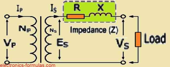
Because of all these losses, now inside the transformer windings we end up with resistance and also reactance together, and these two things combine and form an impedance path, so the secondary output current, which we can call IS, has no option but to flow through this impedance, just like we see in the diagram.
Now since the secondary winding is not pure copper wire but has resistance and reactance mixed in it, then obviously some internal voltage drop must happen inside the transformer windings, there is no escape from that.
How much this voltage drop will be, that depends on two things, one is the effective impedance of the winding and the other is how much load current is being drawn, and this relationship is already known to us from Ohm’s Law, which simply tells us that V = I * Z.
So now, if we watch carefully what happens when the secondary load current increases, then we will see that the voltage drop inside the transformer windings also increases along with it.
And since the primary supply voltage is kept constant in this situation, then the only possible result is that the secondary output voltage must fall because that extra voltage is getting eaten up inside the winding itself.
The impedance which we call Z of the secondary winding is not one single thing, it is actually the phasor sum of two parts, one is the resistance which we call R, and the other is the leakage reactance which we denote as X.
Each of these parts causes its own kind of voltage drop across it, and together they decide how the final secondary voltage behaves under load. So now we can define the secondary impedance along with the no-load and full-load voltages as follows:
Impedance, Z = √(R2 + X2)
So we can define the no-load voltage of the secondary winding of a transformer as:
VS(no-load) = ES
Likewise we can define the full-load voltage of the transformer as:
VS(full-load) = ES - ISR - ISX
or VS(full-load) = ES - IS(R + jX)
∴ VS(full-load) = ES - IS*Z
So now let us see what is really happening here, then if we look at the transformer winding properly, we can understand that it is not some single thing, it is actually made of a reactance sitting in series with a resistance, so the load current flows through both of them together, no shortcut there.
Now since resistance is involved, then voltage and current move together, they stay in sync, what we normally call in-phase, so because of that the voltage drop across the resistor, which we write as ISR, has to follow the secondary current IS exactly, same timing, no delay.
But then if we shift our eyes to a pure inductor, which has inductive reactance that we call XL, the story changes, now the current does not keep up, it falls behind, and it lags by 90 degrees, that is how inductors behave.
So because of this, the voltage drop across the reactance, which we write as ISX, actually goes ahead of the current, it leads it by an angle ΦL, and that happens because we are dealing with an inductive load, nothing surprising there.
Now finally when we talk about the impedance Z of the secondary winding, it is not some separate thing, it is simply the resistance and the reactance combined together, added in a phasor way, so we take both effects and join them using what we call a phasor sum. Each of these components has its own phase angle which we can describe as follows:
cosΦR = R/Z,
∴ R = ZcosΦR, and
sinΦX = X/Z
∴ X = ZsinΦX
ZcosΦ = Z((cosΦR * cosΦX ) + (sinΦR * sinΦX))
ZcosΦ = RcosΦ + XsinΦ
So with V = I*Z we get the voltage drop across the secondary impedance which can be therefore expressed as:
Vdrop = IS(RcosΦ + XcosΦ)
Also because VS(full-load) = VS(no-load) – Vdrop, so we can exxpress the percentage regulation in the following way:
Formula for the Lagging Power Factor
VS(full-load) = VS(no-load) – Vdrop
VS(no-load) = VS(full-load) + IS(RcosΦ + XcosΦ)
%Reg = (IS(RcosΦ + XcosΦ)/VS(no-load))* 100%
So now, when we start talking about a positive regulation expression where cos(Φ) and sin(Φ) are involved, then what we notice is that the transformer secondary terminal voltage does not stay same, it actually goes down, so it falls a bit. That falling voltage is telling us something important, that the load connected is lagging, and lagging power factor simply means we are dealing with an inductive load sitting there.
Now, on the other side, if the regulation expression turns negative between cos(Φ) and sin(Φ), then the behavior changes, so now the transformer secondary terminal voltage does not drop, instead it rises up. This rising voltage is a clear sign that the power factor is leading, which means the load is capacitive in nature.
So basically, the transformer regulation expression works in the same manner for both lagging and leading loads, nothing magical changes there, only the sign changes, and that sign tells us whether the voltage is falling or climbing up.
Because of this, when we see a positive regulation condition, then it results in a voltage drop inside the secondary winding, but when the regulation turns negative, then the voltage inside the winding increases instead of dropping.
Now, even though leading power factor loads are not very common compared to inductive loads like coils or solenoids, they can still show up in real situations, so sometimes when a transformer is supplying a very light load and the current is low, then a capacitive condition can appear and because of that the terminal voltage may rise.
Formula for the Leading Power Factor
%Reg = (IS(RcosΦ + XsinΦ)/VS(no-load))* 100%
So when we have a positive regulation condition it actually causes a decrease or drop in the voltage within the secondary winding of the transformer. On the other hand when we are dealing with a negative regulation condition it leads to an increase or rise in the voltage in that same winding.
Now it is important to note that leading power factor loads are not as common as those inductive loads that we often see like coils solenoids or chokes.
However there are times when a transformer that is supplying a light load with low currents, might find itself in a capacitive condition. This can happen, and when it does it makes the terminal voltage to rise.
Solving a Transformer Voltage Regulation Problem #3
Let's say we have a 12KVA single-phase transformer which is rated to supply a no-load secondary voltage of 220 volts. In case the equivalent secondary winding resistance happens to be 0.022Ω and its total reactance is around 0.08Ω, then let us calculate what will be its voltage regulation when it is connected to a load at 0.85 power factor lagging.
Transformer Voltage Regulation Calculation

To calculate the voltage regulation of a transformer under load we can use the following formula:

Voltage Regulation (VR) = ((V_no-load - V_full-load) / V_full-load) × 100

For a transformer with known equivalent resistance (Re) and reactance (Xe), and operating at a power factor (pf), we estimate the voltage drop (V_drop) using:

V_drop = I_full-load × (Re × pf + Xe × sinθ)

Where:
- I_full-load = Full-load current
- Re = Equivalent resistance (in ohms)
- Xe = Equivalent reactance (in ohms)
- pf = Power factor of the load
- θ = cos⁻¹(pf)

Step 1: Calculate the full-load current
The full-load current of the transformer is given by:

I_full-load = S / V = 12000 / 220 ≈ 54.55 A

Step 2: Determine sinθ
For a power factor of 0.85 lagging:

sinθ = √(1 - pf²) = √(1 - 0.85²) ≈ 0.527

Step 3: Calculate the voltage drop
Substitute the given values:
- Re = 0.022 Ω
- Xe = 0.08 Ω
- I_full-load = 54.55 A
- pf = 0.85

V_drop = 54.55 × (0.022 × 0.85 + 0.08 × 0.527)

V_drop = 54.55 × (0.0187 + 0.0422) ≈ 54.55 × 0.0609 ≈ 3.32 V

Step 4: Calculate voltage regulation
Voltage regulation is given by:

VR = (V_drop / V_full-load) × 100

Substitute V_drop = 3.32 V and V_full-load = 220 V:

VR = (3.32 / 220) × 100 ≈ 1.51%

So the Final Answer is:
The voltage regulation of the transformer at a 0.85 power factor lagging is approximately 1.51%.
Conclusions
So in this tutorial about Transformer Voltage Regulation, we already understood that when the transformer secondary winding is put under load then its output voltage does not stay fixed, it starts changing, so now it depends on what is connected at the output.
This voltage change can be shown as a ratio or mostly as a percentage and when nothing is connected, means no load at all, then no current flows in the secondary winding, so naturally the voltage stays at its highest level.
But once the transformer is fully loaded, then current begins to flow through the secondary and because of that, losses come into the picture, like core losses and copper losses inside the winding.
Core loss is more or less constant, it happens because of the magnetic circuit of the transformer and it mainly depends on the voltage applied to the primary winding, so it is always there whether load is light or heavy. Copper loss is different, it keeps changing, because it depends on how much current the load is drawing from the secondary winding.
Now when these losses change due to change in load current then the system ability to hold voltage steady also gets affected, so in regulated power supply circuits, a transformer with better voltage regulation means the secondary terminal voltage stays more stable even if the load keeps going up and down.
We also saw that the secondary terminal voltage usually drops when the power factor is trailing, like in inductive loads so then large secondary currents may start flowing, especially if the lagging power factor is very low, and that leads to poor voltage control because the voltage drop across the winding becomes bigger.
On the other side, when the power factor is leading, like with capacitive loads, then the output terminal voltage can actually rise, so now this tells us that the winding voltage falls during positive regulation and rises during negative regulation.
Finally, even though zero-voltage regulation is not possible in real life, and only ideal perfect transformers can achieve that, the lowest regulation and best efficiency usually happen when copper losses and core losses are almost equal, so then the transformer works in its most balanced condition.
References: