

Wondering how to build a tone generator circuit whose frequency could be changed or adjusted simply by moving a magnet near its sensor coil? This article will explain exactly how to do it.
The following tone generator circuits use permanent magnet to regulate the inductance of a coil. The inductance value of a coil wound on a ferrite core is principally decided by the amount of turns of wire and permeability of the core material.
Should a permanent magnet be moved toward a ferrite core, the permeability of the core will change in unison to the strength of the magnetic field.
It also has a relationship with the inductance of a coil wound on the core which will be altered accordingly.
The schematic in Figure 1 employs an external horseshoe magnet to cause variations in the frequency of an audio-tone generator.


The tuning range of that circuit is around 2-to-1. Inductors L1 and L2 are wound on a ferrite core that measure 0.25 inches in diameter and 4 inches in length. You may use any similar sized ferrite rod for this circuit.
Inductor L1 comprises 70 feet of 26-gauge copper wire wound on the ferrite rod from one end to another. Inductor L2 is formed by winding 20 turns of 26-gauge wire over the center of L1.
When a 1 µF, 100- WVDC Mylar capacitor is utilized for C1 and C2, you’ll get an oscillating frequency of 1500 Hz. The frequency will be boosted to about 3400 Hz with the magnet having contact with the coil in a parallel position. The first effect of the magnet is recognized from a distance of 2.5 inches.
The circuit doubles as a CW (code) oscillator and tuned for just the correct sound with the magnet. Or, it is contained in a non-metallic case and flipped for making some noise.
By modifying the values of C1, C2 and L1, the circuit in Figure 5 can be switched into a variable frequency RF generator.
We now use a 2- by 0.5-inch, horizontal bar, ferrite AM-broadcast antenna coil for L1 and a pair of 680 pF capacitors for C1 and C2. Using this setup, the oscillator will tune from 600 kHz to more than 1.5 MHz using the same horseshoe magnet.
Magnetically Tuned Crystal Radio

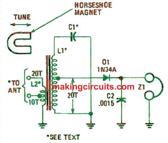
The crystal radio circuit described in Figure above substitutes the difficult-to-set broadcast tuning capacitor using a fixed capacitor and a horseshoe magnet. You can use any ferrite AM-broadcast antenna coil that is at least 2 inches long for the circuit to work.
Furthermore, you can choose a horseshoe magnet with a tiny 1- to 2-inch gap between poles for fine tuning. The flexibility of the tuning range is proportional to the strength of the magnet.
How to Wind the Coils
On the ferrite coil, unwind the turns 20 times from either end and fix a tap at that point, and rewind the wire again. At the same end of the coil (where you tapped), wind 20 turns of 26-gauge wire with a tap at the 10th turn. That winding will act as the antenna and ground input for the receiver.
Using a piece of wood or any non-metallic material, you can construct the receiver using the breadboard style.
After that, utilise two plastic cable-fixing clips to arrest the ferrite core firmly to the breadboard’s base. Arrange the magnet like in the figure where each pole is directed at opposite ends of the ferrite core and at identical distances.
If the magnet occupies a hole through the curved section, a little knob can be affixed to permit simpler tuning of the circuit. Leave the magnet flat on the breadboard’s base and slide back and forth parallel to the coil.
How to Test
Testing the crystal set is a simple process. If a long wire antenna (50 feet or more) is available, you must attach it to the 10th turn on L2. However, this can only be done if a short wire is connected to the end of L2, furthest from ground.
The magnet controlled radio receiver will work seamlessly when the circuit ground is secured to a good earth ground.
It almost never happens that the receive will tune the entire broadcast band with a single-value tuning capacitor, so try a 150 to 250 pF unit for C1.
After that, look how much of the band can be covered. The value of C1 will determine the receiver to its lowest tuned frequency when there is no magnetic influence.
As the magnet comes closer to the ferrite material, the frequency of the tuned circuit will rise closer to the upper limit of the broadcast band.