

This vehicle distress signal lamp flasher circuit design possesses a couple of headlamps 12V and 50W which alternately toggle. This implies that if one light turns ON the other stays off and then alternately flash. It may be applied to the rooftops of ambulances or to signal that a vehicle is unable to move due to some unpredictable reason during nighttime.
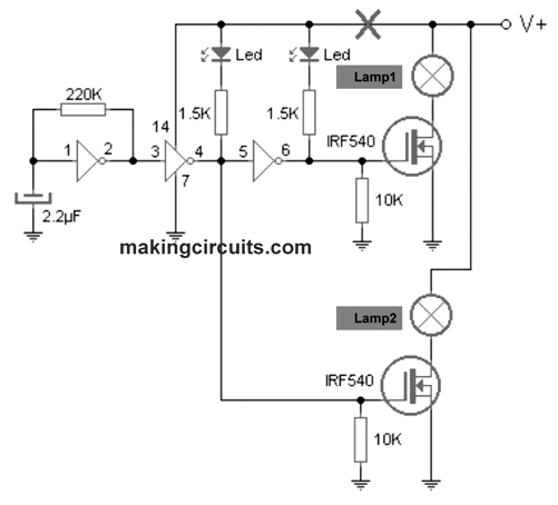

The circuit is very straightforward. The first stage includes an oscillator about an inverter gate. This oscillator generates 2 Hz periods meaning that in a single second the output moves from high to low two times. From the finish of this oscillator have got an additional inverter gate which is accountable for governing the combustion of one of the headlights (and its inner LED) and output this to a 3rd gate is in charge of governing the 2nd lamp and LED. The gate relating to the first and second lamp activates, as soonas the first switches off the second illuminates and vice versa.
For the flash to be quicker or slower you may simply modify a few values 2.2μF capacitor and resistor 220K. The IC that we use is actually a CD40106, that is built from 6 investors CMOS gates. You could employ some other containing comparable attributes.
The power-supply is 12V. If you wish to operate at 24V (for a truck or trailer) just cut off the track connected to power (exactly where it is marked with a cross) and adding a LM7812 regulator.
Lastly the power devices consist of two N-channel MOSFET that make it possible for effortless handling as much as 20A (in fact the supplier claims these function flawlessly even upto 28A). Needless to say, the devices should be effectively dissipated in order to avoid the temperatures related damage.