

Zener tester is a device used for measuring zener voltages and also for plotting variation of zener voltage with zener current. Zener testers find its use in the lab equipment very often. The breakdown voltage is the voltage below which zener diodes stop working.
Why Zener Tester Equipment is so Crucial
Most of the time it is printed on the zener diode case with its specifications. For example in a BZY88 6V8 family zener voltage is 6.8V. But, sometimes you may find complex unique codes.
To know about diode specifications one has to find it in the relevant data book with reference to given code.
Moreover, if a diode is not in use for a long time, printed specification gets rubbed causing more difficulty in knowing its specifications. Therefore, a zener tester is an important and reliable lab equipment.
How a Zener Diode Works
Reverse characteristics play an important role in the functioning of a diode. At voltage below the zener voltage specified the device draws very little current. On reaching the breakdown voltage, if voltage is further increased a large increase in current takes place.

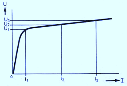
Diode starts working as a constant voltage device. A finite internal resistance also known as dynamic resistance is present in the diode. Due to the voltage drop across this dynamic resistance zener voltage varies slightly with current. This is the reason behind quoting zener voltage at a certain current(5-10mA).
There is also an alternative to the zener tester. Voltage across zener diodes can also be tested by using a battery, series resistor and a multimeter.
The current flowing through the zener diode will be measured by the value of the resistor and the difference between zener voltage and battery voltage.
The voltage difference measured becomes less for high voltage zeners in comparison to low voltage zeners. Therefore, it leads to an error in measurement.
How the Circuits Works

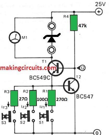
The zener tester used here feeds a constant known current to the zener. A choice of seven different zener currents is also given, to plot zener voltage vs. current characteristic curve.
If the emitter voltage rises above the 0.6V base emitter knee voltage of T2, then more current will be drawn by T2. This results in lowering of base voltage of T1 and thus emitter voltage is also reduced.
If the emitter voltage of T1 tends to fall below base emitter voltage of T2, then less current is drawn by T2. The collector voltage will rise along with emitter voltage of T1. A constant voltage of approx. 0.6V appears at the emitter of T1 due to this negative feedback system.
If one or more of the switches S1 to S3 is closed, a current I equal to I=0.6/R having units (A,V, ohm) starts flowing through resistors R1-R3. R is the parallel combination of R1,R2 or R2,R3 or R1,R3. The current I above flows through zener and the T1. After that a multimeter is connected and zener voltage is measured. A high resistance should be connected of the range 20,000 ohm/ volt or higher.
The high resistance is given so that too much current can't be drawn from zener. If the switches are pressed in different combinations, seven different zeners currents can be obtained.

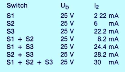
A table above is shown that gives the zener current for different combinations. The actual currents may vary around 10% from given data. The variation is due to the resistor tolerance and temperature coefficient of T2.


Figure above shows the value of different zener currents obtained for different zener voltages by plotting a graph between the two. The ratio of increment in voltage to the increment in current gives the dynamic resistance.
Rd = ∆U/∆I
where Rd is dynamic resistance, ∆U and ∆I are voltage and current increments.
The maximum voltage between the positive supply and the collector of T1 without saturation of T1 is about 23V. Thus, a maximum of 22V zener voltage can be measured. The circuit can be modified for high voltage zeners measurement. It can be done by connecting a high voltage transistor T1, but the dissipation of T1 or zener should not exceed high current ranges.
Zener current is only determined by the T2 base- emitter voltage and resistance R1-R3. Therefore, a stabilized supply is not compulsory. A circuit consisting of 18V/50mA transformer, 30V/50mA bridge rectifier and 470u/35V capacitor forms an adequate unstabilised supply.
Another Zener Diode Tester Circuit
This zener diode tester circuit is surely an add on unit for any multimeter possessing a sensitivity of 20k/V or more practical, also it permits a tough check to be built on zener diodes having using voltages as high as around 33 volts.
The zener diode tester circuit functions from a regular 9 volt battery no line supply or special high voltage battery simply being needed.


In an effort to receive a very well high voltage with this application from an standard 9 volt DC supply you need to have a voltage step up circuit of some sort.
In this instance, an sound oscillator employing IC1 is utilized to drive the primary winding of step up transformer T1, providing around 50 V AC through the secondary winding.
T1 is really designed for use like a step down transformer in transistor amplifier output stages, however it supplies adequate outcomes when used in reverse to provide a voltage step up.
The output through T1 is halfwave rectified and filtered by D1 and D3 to present to offer an unloaded DC supply of around 75 to 80 volts (around 40 to 50 when loaded).
Along with SW1 at the 'low' position, a current of approximately 1 to 2 mA (based upon the voltage of the zener under test) is provided to the test device by means of current limiting resistor R4, when SW2 is controlled and power is placed on the circuit.
The multimeter, which can be turned to an suitable DC voltage range, is linked in parallel using the test device and registers its zener voltage.
Switching SW1 to the 'high' selection leads to around double the last current to flow with the zener which is being tested ,as a lower value current restricting resistor (R3) is now turned directly into zener diode tester circuit.
When the test device is completely functional this certainly will trigger just a very little boost in the meter reading and generally there could well be no visible change in the meter reading at all.
T1 could be almost any form of small transistor output transformer. A 500R CT to 8R sort will continue to work good.