For clock generators which are used in microcontrollers, the designs are mostly crystal based. You may say crystals have become cheaper over the years, yet they are compatively expensive ieven today. In contrast to this a ceramic resonator seems to a much cheaper alternative to the conventional crystal devices.
When it comes to making a 1 MHz time base generator circuit, we nomaly do not consider the 6th significant digit too important, however high frequency does become a crucial factor, and this is certainly guaranteed by a ceramic resonator filter device.
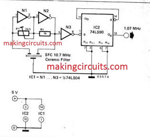
The proposed circuit is designed to generate a precise 1.07 MHz frequency which becomes ideally suitable for any microprocessor based application.
The circuit looks quite self explanatory, since it only includes a couple of ICs as the main active components.
The oscillator section is built around N1, N2, P1, R1and the ceramic resonator filter device. The output of this stage is fed to an inverter gate N3 which helps to improve the signal slope.
After this the resultant signal is sent to input B of the decimal counter IC2. Due to the fact that the Qd output is fed back to input A the frequency from the available output at Qa becomes precisely 1/10th of the oscillator frequency.
You can also connect in order to provide a clock frequency of 2.14 MHz, which may be useful for some specific MCU users.
It is also possible to incorprate this 1 MHz time base generator circuit with a 45.5 kHz ( or 90.1 kHz in case a 5:1 division is finalized)
One thing would be worth noting regarding the IC 74LS690, unlike traditional set ups, the power supply inputs will be across pin#5 Vdd, and pin#10 Vss.