

The post explains a simple universal automatic 12V battery charger circuit which can be used for charging all types of batteries regardless of the current capacity or the AH level. Meaning you can this charger for charging a 1AH battery or a 1000 AH battrey, just by upgrading the transistor.

Either due to the fact most of us stop using the car for long periods or for the reason that battery is about to run out, this circuit enables to load it effectively and indicate by means of an LED as soon as the charging process is completed.
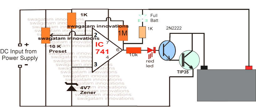
As can be found the circuit is an automatic battery charger circuit, consisting of an operational amplifier that is responsible for governing the state of the battery to identify the actual time by which it should stop charging the battery and trigger the LED indicator.
The three-stage resistive divider enables you to make reference voltage for the operational amplifier. In this manner, the battery cut-off takes place when the current drops under the half-ampere, and the circuit starts to oscillate by operating the transistor that switches current to the LED resulting in it to glow and indicate the full charge level of the battery.
Remember that the bridge rectifier for the input power supply may need to be above 10 amperes (voltage equal to or greater than 50V) therefore it is certainly not for soldering in printed circuit rather needs to be screwed to the metallic cabinet of the apparatus and hook up by crimped terminals.
The original filter capacitor could be bolted up onto the plate or could be twisted in the cabinet by using a couple of plastic seals and joined in parallel with the positive and negative terminals of the rectifier bridge. The typical switch will be of the style employed in electric coffee machines that include neon gas lamp which signals if the charger is switched on.
Seriously consider how this switch is actually attached because it is quite common to mistake the terminals and short circuit the 220V line. In case preferred, a DC ammeter may be inserted in line with the positive terminal of the output on the battery in order to visually keep track of the current of the battery.
This device could be comparable or electronic digital battery charger, despite the fact that these days it really is a lot more jazzy these digital ones. The positive terminal of the device links to the circuit as well as the negative would go to the battery (in the direction of its positive terminal).
You possibly can put a buzzer that will sounds simultaneously in conjunction with the LED triggering. This should be attached between anode of the LED and the emitter of the transistor and needs to be of the electronic piezo type, having oscillator a part of its internal circuitry.
In order to apply it just connect the battery to charge, switch on the system and push the pushbutton that will begin charging. Once the charging is accomplished, the device LED will illuminate and the unit should be switched off and the battery taken out of the terminals.
How to Set up this automatic universal battery charger circuit
Suppose you want to charge a 12V 200AH battery charger circuit. You will need to complete the following initial procedures:
Do not connect the battery as yet, first apply a 14.4V from the DC input side, and adjust the 10K preset such that the green LED just lights and the red LED just shuts off.
That's all, you are done.
Now connect the 12V 200AH battery, switch ON the input from a DC 14.4V 20 amp source and let the battery begin charging.
You will the red LED glowing while the battery is charging, and as soon as it reaches 14.4V, the red LeD shuts off and the green LED lights up indicating the full charged status of the battery