The 12 V battery charger explained in the following post is virtually indestructible, as it is full protected against output short circuited or battery with over load current. Meaning, the battery charger will never burn or get damaged regardless of the output situation, and will enable the connected battery to charge with the pre-programmed voltage and current ratings
NOTE: The battery charger explained in this article has been specially developed for charging 12 V lead-acid batteries. 6 V batteries can be charged but be informed there will be no automatic voltage cutoff. Therefore, the 6 V batteries must not be always attached to the charger.
In a glance, it would seem a handful of circuits are easier to design than a battery charger. The truth, however, is far from it. In our research, we weren’t able to rule out a single unit that promised protection against misusing the charger – which was essentially the most important aspect to consider. A fully protected charger should comprise:
- Function during a short circuit.
- Undamaged by charging attempts or a reversely-connected battery.
- Function into a completely flat battery.
- Regulated for voltage and current.
- Able to float a fully charged battery for prolonged periods.
Interestingly, the short circuit proof battery charger checks all boxes. As both voltage and current regulation are included, the unit will first charge at its peak current limit of 4 A, then as the voltage of the battery escalates, the charger automatically switches to a voltage limiting mode (maximum 14 V).
In this voltage regulation mode, the current will be seen in pulses with fairly long intervals between them, and the LED will prominently flicker if the current drops to 1 A or less.
On batteries of 30 Ah rating or less (which is good), this flickering of the LED shows the fully charged condition. When you use older batteries or anything with over 30 Ah rating, the float current can never drop lower than 1 A on most cases thus no flickering is visible.
On some necessary applications, the batteries may be ‘floated’ steadily across the charger without destroying the charger or battery. Primarily, this device is self-starting for batteries that are already charged to 4 V or over.
In case the batteries are completely flat or have less than 4 V, a starting button may be needed to commence the charging cycle. After some time, the battery voltage would have increase to maintain operation.
The charger will not begin if a battery is attached to it with reversed polarity even if you keep pressing the start button.
Also, you need not worry if the charger will be damaged if the output leads are accidentally shorter together – it would not. Furthermore, the protection fuse will blow if you attempt to press the start button while shorting the leads. However, this last condition will less likely to happen and fundamentally, the fuse is included as a precautionary step.
How It Works
To be precise, the battery charger is a switching regulator limiting the output voltage to 14 V and the output current to 4 A. Due to that, there are two modes of regulation – current and voltage.


The changeover between this pair of modes is quite severe. If there is an increase of 0.1 V on top 14 V, it will cause the output current to drop from 4 A to 0 A.
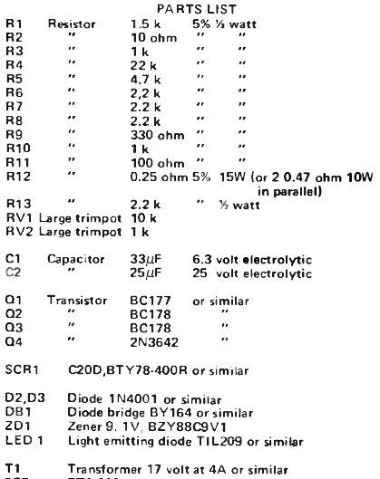
The 17-V secondary of Transformer T1 is bridge-rectified by diode bridge DB1 to deliver pulsating DC to the regulator.
The chief control element is SCR1, the gating sensitivity of which is elevated by transistor Q4. With a current of 2 mA via R1, it is enough to switch on Q4 and SCR1.
Current will channel via R5 and the base-emitter junction of Q1, turning it on when a battery is attached with the correct polarity across the output terminals. This generates current in R1 which is enough to turn on Q4 and subsequently SCR1.
The current flowing through the latter is detected by R12, and if it more than 4 A (average), Q2 will be switched on and is retained in that state for a short interval depending on the charge on C1. So, the switching on of SCR1 on the next half-cycle is postponed.
As a result, the average current is reduced. The control action makes sure that the current steadies at 4 A.
Once the battery reaches the 14 V mark, transistor Q3 will be switched on where the turn-on point is set by RV2. Again, this deters SCR1 from switching on until after some time by overtaking the base current of Q1. So, the current continues to drop until the voltage across the battery stabilises at 14 V.
Adjustment
To adjust the charging current, use an ammeter (10 A range) in series with a flat battery. Then, adjust RV1 for a 4 A charge current.
You may also use a 4 A or 5 A ammeter range provided the meter does not come with internal diode protection. As an alternative, you may adjust the voltage across R12 using RV1 to 1 V while charging a flat battery. In this case, it is recommended to use a 2.5 V or higher meter range.
When adjusting the voltage, make sure the battery is fully charged, which makes the current to fall. Once it has dropped to 2 A, tune RV2 for 14 V across the battery.
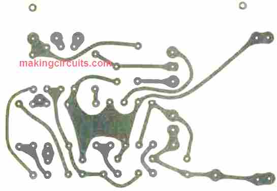
PCB Design