


The article clarifies how to get an affordable yet effective remote controlled trolley which is usually maneuvered left, right, forward and reverse as demanded, by the user making use of the offered remote handset. The plan would not rely upon an MCU circuit.
In one of my prior content I highlighted relating to an easy remote controlled toy car circuit, the present idea of a remote controlled trolley is influenced with the exact same idea but is designed to be utilized for possessing amazing and considerably bulkier loads.
How the Circuit Works
This design could be especially matched and suitable for malls or shopping retail outlets where it could also be executed as a small transport vehicle for transporting material within the compound or the premise with the use of several presses of the remote Tx unit.
The first task in constructing the suggested remote controlled trolley could be to locate a pair of standard Rx/Tx RF devices either from your local electronic dealer or from any kind of online store, I like to recommend buying from an online store as it will be less difficult and comfortable, although more costly.
The acquired units would appear as proven below:
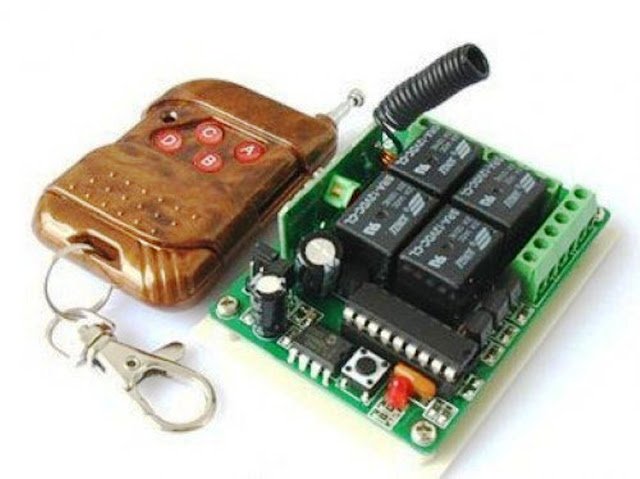
The left side brown color unit is the Tx or the transmitter unit while the adjoining circuit broad is the Rx or the receiver unit.
The Tx unit can be visible with 4 red colored buttons marked as A, B, C, D, as well as the Rx board could be seen obtaining 4 relays (black color boxes).
The four particular buttons of the Tx module are wirelessly paired for functioning the four matching relays of the Rx module.
You will notice connectors fixed around the ends of the board (green colored), these kinds of connectors are correctly terminated with the (+) (-) supply inputs for the Rx board including with the relay contacts, for all the 4 relays.
A relay, as we all know contains 5 basic contacts and their pinouts viz: 2 pins for the coil, one for the pole and one each for the N/C and the N/O.
Considering that there are 4 relays in the Rx unit, it will be easy to find 5 x 4 = 20 outputs connected with the significant connector points.
It might be a difficult process to independently figure out these kinds of relay terminations on the connectors, as a result I would advice soldering wires directly on the relay pinouts in an effort to save yourself from the above process, this work will likely be preferred in the future while we engage the unit with the trolley's control circuit.
Developing the relay control circuit for the trolley
To accomplish this you require a variety of relays and diodes. The relays needs to be accurately rated that allows you to deal with the high power wheel motors of the trolley. I might suggest choosing OEN make relays for this, as proven the following image:
12V, 400 ohms, 10 amp relay


The diodes which can be expected in the relay driver circuit could be our standard 1N4007 diodes.
The circuit particulars for the same could be noticed in this article diagram:

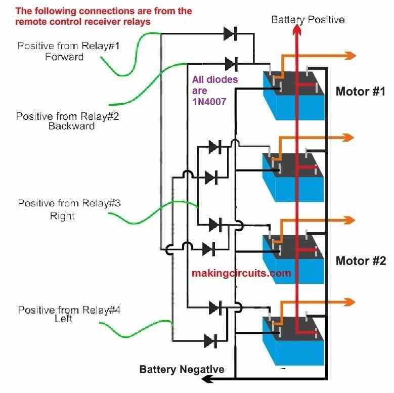
Implementing the above stipulated relays as well as the diodes it is very important to accomplish developing the above relay driver circuit board which can be simply performed on a piece of veroboard.
After this we have now an essential process at our disposal that is certainly establishing the green wires proven in the above diagram with the remote control Rx board.
Before the integration we shall must add a few mods in the Rx module, as discussed below:


Making use of pieces of insulated wires, correctly stripped and tinned at the ends go on attaching (by soldering) all the pole pins of the relay and link this common joint with the positive line of the Rx board.
Right now in this particular condition we could imagine that when the relays are not in an activated situation (through the remote handset) the pole positive input of each relay will likely be connected to their particular N/C points, when activated the positive from the pole would probably shift and get linked with the suitable N/O points.
In other words, on activation the N/O contact are showered with the positive supply as well as we are now thinking about this optimistic supply from the N/O contacts mainly because these will likely be initiated only once the relays are turned on, intending that when the Tx (transmitter) buttons are pressed.
For that reason all the suitable N/O pinouts ought to be linked to the green wires of the above indicated relay driver circuit.
The moment this is accomplished, the Rx will likely be associated with the relay driver module for carrying out all the meant techniques of the remote controlled trolley, that is: the forward, reverse, motions and the left, right turns.
Powering the relay Driver Board
Due to the fact the relays in the relay driver level could well be liable for moving the heavy motors linked with the trolley wheel,the supply because of this might need to be equivalently strong, for that reason deep cycle lead acid batteries emerge as a good choice for this application.
If perhaps the motors to be rated at 12V, a 40AH lead acid battery could well be sufficiently good for making it possible for the trolley to move in spite of bulkier loads.
Configuring the Wheels with the Motors for the Aimed techniques
As could be recognized in the following figure, the talked about remote controlled trolley requires 4 wheels for suporting and rolling the system.
On the other hand simply the front two wheels might be liable for permitting the intended reverse, forward, right and left techniques, as well as the motors could well be required to be clamped with such two front wheels of the trolley, as proven in the following image:
The rear wheels are merely dummy wheels, fixed only for enabling a free rolling of the trolley, as a reaction the front wheel orders.
As could be realized in the above image, the module started as PCB assembly is the relay driver board, the remote module suggests the Rx remote receiver board while the battery is the 40 AH 12V battery which we talked about in the prior a segment of the article.
After assembling you could have to tweak and examine the motor wire connections with the relay driver board.
For a forward and reverse motion both the motors ought to be as one collectively, although for carrying out a right or a left flip, the motors have to pass through an opposite rotational movement.
If you come across the motor not behaving in the above manner, it could be most definitely resolved by simply swapping the polarity of one of the motors. This certainly will quickly correct the scenario and force the motors to apply the selected techniques.
Ultimately the A. B, C, D buttons could be correctly matched or interchanged for the any of the particular techniques by tweaking the green wire links with the Rx module, in accordance with the users choices.