

LC transistor Astable multivibrators or more fondly known as oscillators are one of the most commonly used electronic components when building a circuit. An oscillator is generally sustainable on its own without demanding additional circuitry.
Frequently, these oscillators begin as an amplifier with regulated amount of positive feedback from output to input to start and retain oscillation. This is easily distinguishable – like the sharp screeching noise that comes from a PA if its gain is too much.
Three-transistor LC oscillator
An agile 3 transistor oscillator circuit that operates at any audio and low radio frequencies is shown in Figure 1.

The radio frequencies are using any LC combination for the frequency deciding components. From our diagram, the three transistors are aligned in a Darlington/emitter-follower setup. This delivers an exceptionally high input impedance to the LC combination. That circuit configuration lessens the loading effect on the frequency-determining components.
An easy method to decide the frequency of the LC-tuned circuit is by applying this formula:
f = 5028 / √LC
The frequency, f, is in Hertz whereas L and C are inductance (mH) and capacitance (µF) respectively. Since C1 and C2 are connected in series the sum of capacitance (Ct) can be computed through:
Ct = C1xC2 / (C1+C2)
For instance, you can determine the resonant frequency of an LC combination if L1 is 10 mH and C1 and C2 each is 1 µF. Since both capacitors are in series, you can apply the formula directly.
Ct = 10E-6 x 10E-6 / (10E-6 + 10E-6) = 0.5 µF.
After that, you must multiple the total capacitance by the inductance which yields the value 5. Square root this number and you will end up with 2.236. Divide that with 5028 and the final frequency is 2248 Hz.
Let’s assume you know the target frequency and have a certain coil on hand, the needed capacitance value in µF can be determined by using this formula:
C = 50282 / f2L
Where C is the combined value of the two series-connected capacitors. You must remember that the series value of C1 and C2 must be identical to the value found through the formula. Once verified to be same, the actual value of the individual capacitors must be twice as much from the calculated value.
For example, if the required capacitance is 2 µF and the capacitors have the same value, the individual capacitors must have a rating of 4 µF. It is good to know that capacitors in series divide like resistors in parallel.
The LC tuned circuit suits the transistor circuitry when C2 is bigger than C1 (at least 2 to 3 times). If you have the needed frequency and a capacitor on hand, the needed inductance (L) can be found by
L = 50282 / f2C
The receiver element from a telephone handset can be utilised for L1, and two 4.7 µF, 35 V tantalum capacitors are suitable for use for C1 and C2. It is important that you identify the polarization of C1 and C2 as showed in Figure 1.
This helps to generate a 700 Hz tone that is audible from the inductor. The oscillator works best on small inductors and huge capacitors. This property is useful when generating extremely low-frequency tones without isolating the large inductor.
Potentiometer R4 configures the positive feedback and must be regulated for the best waveform. If an oscillator is flexible, observe the output of C4 and reduce R4’s value, beginning from its maximum resistance until the circuit begins to oscillate.
Resume turning R4 in the same direction until the waveform starts to display a little bit of distortion. After that, invert the turn direction of R4 until the waveform presents symmetrically.
One-transistor LC oscillator
Resembling the previous circuit but with the tendency to function at a much higher frequency, the single transistor LC circuit in Figure 2 was examined.

The upper frequency limit of that circuit is configured mainly by the transistor. The L and C values are chosen the same way as for the oscillator in Figure 1.
On the other hand, the oscillator circuit in Figure 3 displays a decent choice for a very low-frequency, audio tone producer.

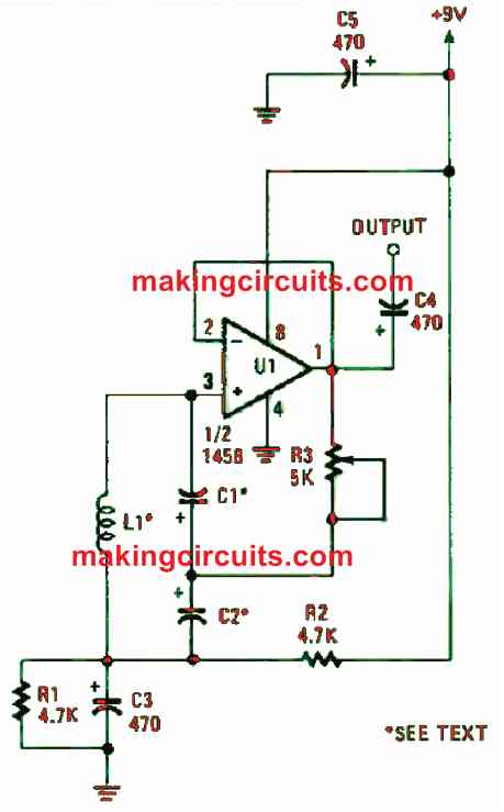
Using the above op amp LC oscillator circuit, you can get tone frequencies under 10 Hz and even less than 1 Hz. Here, on half of a 1458 dual op-amp functions as the active component and the LC tuned circuit is identical to those utilised in the previous two circuits.
You will realise that the LC-tuned circuit resonated at or under 10 Hz, and you’re dealing with huge inductors with values about 10 H and higher. These are both difficult to procure and too expensive.
However, we don’t have that problem because the LC oscillator circuit in our experiment is adaptable to any inductor of your choice.
By going through some scrap electronic components, you can find the inductor you need. Any power transformer’s primary winding can be utilised for the inductor.
Some of them have a low and high of 3 to 10 Henries. The best option would be a variable autotransformer that is constructed for 114 VAC, which you can find in common electronic stores.
How to Tune the LC
You can also find a useful inductor for the tuning the LC oscillator to a very low frequency range from a high-voltage ignition transformer. Just attach the high-voltage output terminal and one of the primary terminals to the circuit. This way, you’ll be able to get close to a frequency of 1 Hz.
When tuning the 10 H coil to a frequency of 5 Hz, we found deploying one of the formulas above, a 100 µF capacitor is required. Since C1 and C2 are in series, the capacitor each should have a value of 200 µF. Because this is a flexible circuit, electrolytic capacitors can be used for C1 and C2.
It is fundamental to know that when applying the formulas with large inductors, the value of 1 H = 1000 mH.
Several LC tuned circuit combinations (those tuned to very low frequencies) need R3 to be set close to the low-resistance end of its rotation. If you notice the outputs are inconsistent, swap R3 with a 500 Ω potentiometer. This makes regulating the circuit’s feedback much easier.
The “Q” of the huge and cheap inductors is generally low. Hence, it required a bigger circuit gain to retain oscillation. You may use coils which are utilised for 100 Hz and beyond for better oscillation as they have higher “Q” and demand less feedback.