This bass booster amplifier circuit can be used for generating high power throbbing bass effects, into any connected speaker system.
While in no chance influencing the normal output or stereo separation of the current system the booster successfully includes the bass signals through the left and right hand stereo channels and, subsequent amplification, thrives them via a common bass speaker.
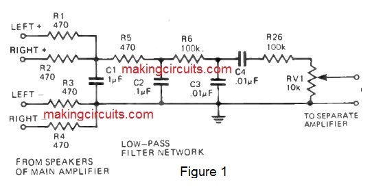
The system can be employed in a number of various methods. In the easiest form, the combining filter demonstrated in Fig. 1 is linked to any kind of spare mono or stereo amplifier (rated at 20 Watts or even more) and performed by way of a single speaker enclosure that includes a good bass result.

In another form a similar arrangement is utilized alongside the speaker system manufactured for bass reproduction.
But since couple of us have spare high powered amplifiers lying about waiting for a project just like this we have got developed a simple but beneficial amplifier particularly for this specific project.
Please note, that with this latter arrangement the design of the filter continues to be changed somewhat.
CONSTRUCTION
In case the booster is employed within the easiest form utilizing a separate amplifier the filter needs to be built on a small piece of perforated board or tag strips.
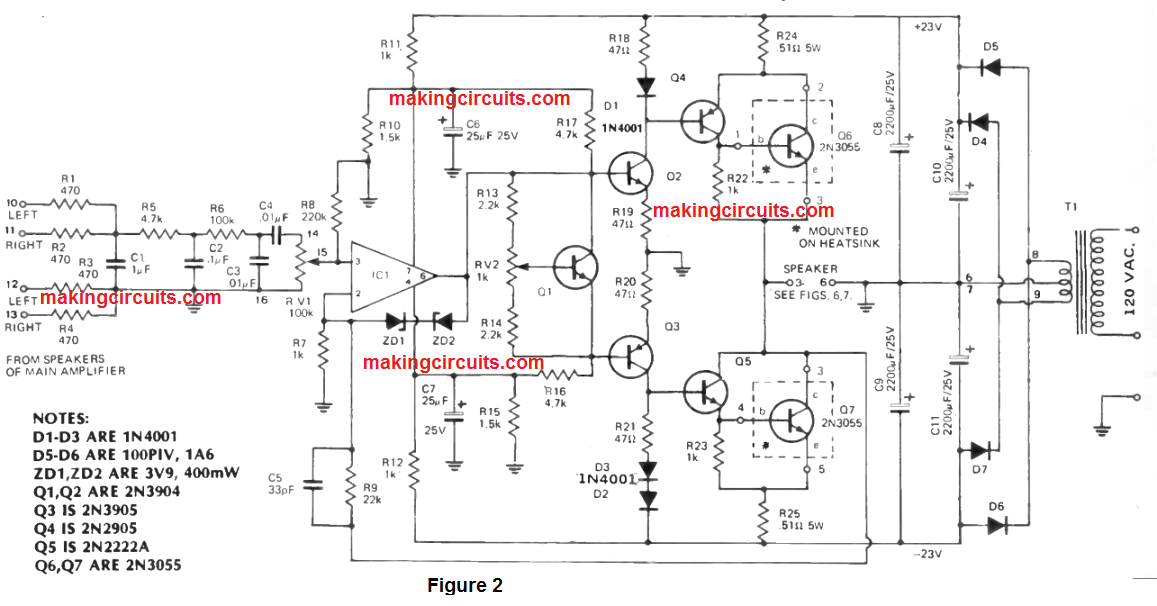
The circuit is displayed in Fig. 1. The layout is not very essential. In the form demonstrated in Fig. 2, the amplifier and filter are designed as one unit.

This complete unit might be installed within the new bass speaker enclosure (as we did with our prototype unit) or positioned in any kind of easily available place.
When you find yourself satisfied that all components happen to be wired the right way, set the wiper RV2 centre of its travel.
Tend not to link the speakers at this point of the procedure. Turn on the main 120 Volt supply and verify terminals. This certainly will be lower than 200 mV.
In case it is significantly higher than this, shut off and recheck all connections. (If a voltmeter is not accessible, link one side of the speaker to one side of the amplifier and momentarily touch the second amplifier lead to the rest of the side of the speaker.
If all is well the speaker need to stay practically silent or almost develop a slight 'click'. (If the speaker cone attempts to fly across the room then turn off immediately and recheck all connections).
After that, if a milliammeter is accessible, disconnect the lead to pin 2 and measure the current with this lead. Adjust RV2 till the current around 40 mA. If no millianimeter is obtainable, leave RV2 in mid -position.
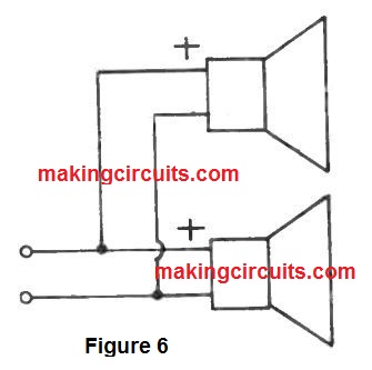
Connect the leads through the present speakers to the filter input and link the bass speaker to the booster amplifier. The power might now be turned on and also the complete system inspected.
Do not forget that the sound from the bass booster circuit is going to be highly altered if this unit is required alone but when mixed with the sound through the existing two speakers in your stereo system it sounds just great.
BASS SPEAKER ENCLOSURE
The enclosure tested for use with this method is revealed in Figs 4 and 5. The speakers utilized were two 8 ohm types linked in parallel, therefore possessing a highly effective impedance of 4 ohms.

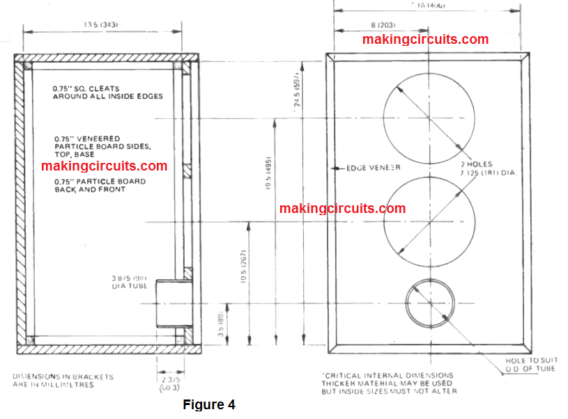

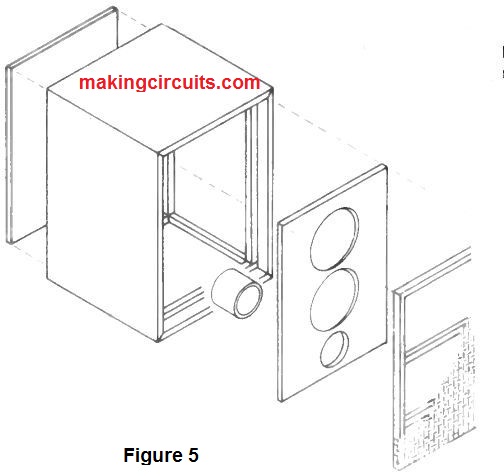
The inside of the speaker enclosure was lined on at least three non -facing surfaces (eg side, top and rear) along with absorptive material such as felt.
How it Works
The output through each channel of the present stereo amplifier is put together by resistors R1 ,R4. Resistors R6, R6 and RV1, combined with capacitors C1, C2 and C3 form a low pass filter that includes a cut-off frequency about 200 Hz and a final 18 dB per octave slope.
Capacitor C4 provides for a high pass filter of around 30 Hz to preserve the speakers from big transients and dc levels. (The filter demonstrated in Fig. 1 designed for use with individual amplifiers provides a 20 dB attenuator included prior to the output potentiometer this safeguards the following amplifier towards overloads).
The amplifier displayed in Fig. 2 has a voltage gain of 23x(R9 + R7)/R7 a power output of around 25 Watts into four ohms and a frequency result from 0 Hz to around 50 kHz
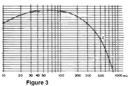
Along with the input filter incorporated, the frequency response of the bass booster amplifier is that of the filter displayed in Fig. 3. The main voltage gain of the amplifier circuit is made available from IC1, Q2 and Q3. Q4 and Q5 provide the essential current gain to run the output transistors Q6 and Q7. Transistor Q1 compensates Q4. D2 and D3 compensate Q5 and Q7.

Zener diodes ZD1 and ZD2 protect Q2 and Q3 by limiting the output voltage swing of the IC. The powerful bass booster amplifier described in this particular project could also be used without the filter as a easy 25 Watt mono amplifier in this case diode D2 or D3 (but not both) needs to be taken off its position on the printed circuit board and transferred on the heat sink.