

Here we learn how to build a simple back EMF dependent 220V drill speed controller circuit, which allows the drill machine torque to increase proportionately as load increase.
It implies that once the drill gets loaded, the power of the torque keeps enhances as the load o the drill bit increases This enables to drill machine to cope with tough walls and concrete and never stops from forging ahead with its drilling operation even under substantial loading.
Overview
This easy circuit will be appealing mainly because it allows drill speed to be governed regardless of the load on the drill.
The planning makes use of the idea that as the load current enhances the back EMF of the drill drops thereby the current heightens.

It is apparent, checking out the circuit diagram, this circuit is not difficult, and the very same will also apply to its functioning.
How the Circuit Works
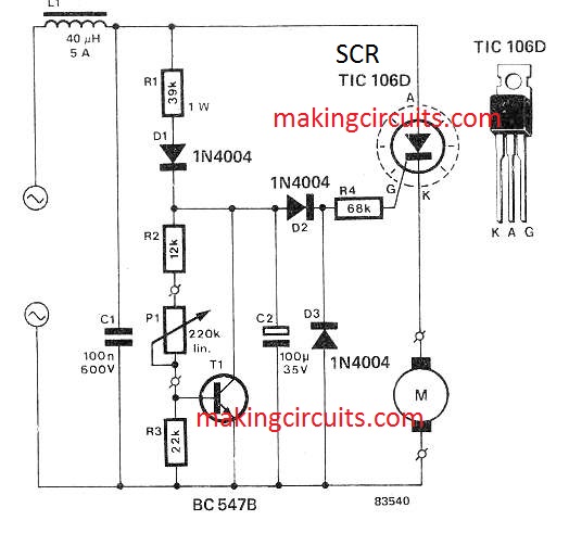
Throughout the positive half-cycles of the mains C2 is charged up via R1 and D1, so that the voltage across this capacitor is identical to the 'zener voltage’ of the circuit at T1.
The circuit configured around T1 is an adjustable zener where the zener voltage is identified with the setting of Pl.
Actually the voltage between collector and emitter is characterized by the ratio between resistors R3 and R2 + P1.
The voltage drop throughout R3 is definitely add up to the base-emitter voltage of T1 (0.6 V) therefore it implies that the zener voltage may be expressed as:
(P1 + R2 + R3)0.6 / R3.
The motor is not really hooked up in the normal position at the start of the circuit, rather alternatively it is soon after SCR 1.
The firing time of SCR 1 is hence outlined by the difference between the zener voltage and the back EMF of the motor. In case the motor gets a lot more intensely loaded, the SCR is going to trigger sooner.
Simply because an SCR is employed the circuit can merely control 180° of the supply cycle; therefore with this particular circuit it is far from feasible to alter the drill speed via O to 100%, however this type of controller is solely utilized in low speed purposes.
A drawback of this simple drill speed controller circuit could be that the motor ‘stutters' a little bit while it isn't under any load nevertheless this outcome fades away as soon as there is a load on the drill.
Inductor L1 and capacitor C1 are accustomed to filter out high frequency influences brought on by phase-chopping. The SCR needs to be installed on a heat sink to guarantee efficient cooling down.
Another Design
The second drill speed controller circuit explained in this article permits endless variation of speeds from zero to around 75% of full speed, and is also presented along with a switch to enable normal full speed operation without disconnecting the drill through the controller.
The controller has constructed in compensation to retain significantly constant speed irrespective of changes in load.
CONSTRUCTION


It should be highlighted that the controller is linked right to the lines without the using of an isolating transformer.
Proper care should be taken using the construction to make sure that there is absolutely no likelihood of any kind of harmful circumstances developing.
The SCR employed is a stud mounting form and is installed by making use of the solder lug, provided with it, soldered onto the center lug of the switch.
For loads around 3 amps no other heat -sinking is needed. In case a plastic pack SCR is utilized a hole might be drilled with the switch lug and the SCR bolted right to it.
Even so in this instance it is important to place a piece of aluminum (around 25 mm x 15 mm) amongst the SCR and switch lug to work as a heatsink.
Do not forget that, considering that the unit functions at 120 Vac all external parts should be grounded. We employed a plastic box having a metal lid. But we furthermore utilized a cable clamp having a metal screw with the side of the plastic box.
This screw needs to be grounded, in addition to the lid and the ground terminal of the output socket. The ground wire needs to be constant which is, it will go from one ground point through to the next and not be separate links.
Two ground wires may be soldered to one ground lug. But under no account should two wires be secured under a single screw. Which includes SCRs it might be observed that the trigger current provided by R1 and R2 is inadequate.
If this is the situation an extra 10 k resistor needs to be used in parallel with each resistor.
USING THE CONTROLLER
Plug the controller into the wall and the drill into the controller. Choose either full speed or variable as needed. Remember that you cannot find any ON/OFF switch presented on the unit and the normal switch on the drill is employed for this reason.
When full speed is chosen the drill will work in most cases and the speed control on the controller could have absolutely no result. At very low speeds it might be identified that drill runs jerkily under no load.
When variable speed is picked, the control will adjust the speed ranging from zero and around 75% of full speed. There might be a dead zone at both low speed and high speed ends of the control.
This really is totally normal and is as a result of various drill qualities and component tolerances within the controller. On the other hand as load is implemented the speed will smooth out.
While using the drill at lower than full speed the cooling of the motor will probably be substantially decreased (since the cooling fan is on the armature shaft and also runs slower).
Therefore the drill could possibly get hotter when applied at low speeds, and extended periods of use within this mode needs to be eliminated.
How it Works
A universal motor, when running, constitutes a voltage which usually opposes the supply. This voltage, referred to as back EMF, is proportionate to the speed of the motor.
The SCR drill speed controller incorporates this result to realise a specific amount of speed versus -load compensation. This controller employs an SCR (silicon controlled rectifier) to gate half wave power to the drill motor.
The SCR will perform as long as a) anode (terminal A) is positive dependent upon the cathode (terminal K), b) once the gate (terminal G) reaches least 0.6 volts positive depending on cathode, and, c) when about 10 mA gate terminal.
By controlling the level of the voltage waveform to the gate we successfully manage the time at which the SCR activates in each forward half cycle. With this indicates we efficiently control the amount of power provided to the drill.
Resistor R1, R2 and potentiometer RV1 form a voltage divider which supplies a half wave voltage of adjustable amplitude to the gate of the SCR. If the motor is stationary the cathode of the SCR will probably be at zero volts and the SCR will switch on nearly completely.
As the drill speed raises, a voltage generates along the drill thus lowering the efficient gate cathode voltage. Hence as the motor speeds up, the power provided reduces till the motor stabilizes at a speed dependent on the setting of RV1.
Should a load be positioned on the drill, the drill will usually decrease, but as the voltage across the drill also falls, more power is supplied to the motor because the SCR firing time is automatically advanced.
For this reason the speed, once set, is managed fairly constant irrespective of load. Diode D2 is employed to halve the power dissipated in R1, R2 and RV1 by restricting the current via them to positive half cycles only.
Diode D1 protects the SCR gate towards extreme reverse voltage. In the full speed position the SCR is merely shorted out by SW1, Hence RV1 loses control and full power is used to the drill.