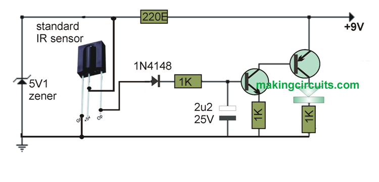
Here is a straightforward TV remote control tester circuit that anyone can use to check TV and VCR remote handsets. The infrared sensor module generates a 5 volt logic pulse sequence in accordance with the digital signals of the specific remote device button pushed.
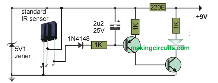
Other sorts of sensor devices can be purchased that are fitted with an inverted operation as confirmed in the second illustration which explains an alternative variety.
In the first circuit, the output is typically minimal without a transmission picked up and thus ends up being a positive running pulse sequence each time a signal is available.
The pulse process symbolizes the digital code of the selected button pushed in conjunction with supplier details. While the pulse sequence is transmitted, the 4.7uF capacitor is fully charged to roughly 3.1 volts along with the capacitor voltage minus a diode forward drop, transpires across the 470 ohm resistor producing a collector current from the BC557 of roughly 5 milliamps.
The collector current of the initial stage runs into the base of the output transistor BC547 which releases around 20 mA into the warning LED.
In case the pulse chain concludes, the capacitor eventually discharges by means of the base of the first stage transistor leaving the LED light to continue running for a approximately 1 second.
The LED is going to work over a large voltage spectrum, so you are able to implement other sorts of lamps from just about any application.
The TV remote control tester circuit is usually powered from a compact 9-12 volt DC, 200 mA or bigger wall transformer. It could possibly also have to have a supplementary 1000 uF filter capacitor around the output in case the wall transformer does not necessitate an integrated cap.
Specifically using a 9 volt power supply, the green LEDs could be swapped over by a white or red LED as well as the output transistors could very well be changed with little signal transistors. The combined current dissipate will probably be approximately 20 mA with the LED illuminated, not to mention 15 mA extra while the LED is off.

Transistors can be BC547 for the NPN, and BC557 for the PNP