In this post we are going to understand how a phase shift oscillator works and we will be constructing one and also simulate output the using software simulation tools.
Phase shift oscillator is a sine wave oscillator which generates the frequency based on connected resistors and capacitors network. The advantage of phase shift oscillator is good stability and can provide distortion less frequency generation with wide range of loads; however for huge loads we may need pre-amplification stage.
The phase shift oscillator has 3 parts, the RC network, amplifier and positive feedback. Let’s look into them in detail.
The RC network consists of resistors and capacitors connected in ladder form, as shown in figure.
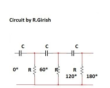

It has three RC stages, each RC stage shift the input frequency by 60 degree. The first stage shifts frequency by 60 degree, second stage shifts frequency by 120 degree and third stage shifts frequency by 180 degree.
The next stage is amplifier, which can be a transistor based amplifier or operational amplifiers. The amplifier stage generates 180 degree phase shift, which gets input from the RC network. So combining both phase shift from RC network and amplifier’s phase shift 180 + 180 = 360 degree.
To get the frequency from the circuit consistently, we need to provide positive feedback to the circuit. There are two types of feedback, positive and negative feedback. Here is general meaning of those:
Negative feedback is feeding the output signal to the input with 180 degree phase shift.
Positive feedback means feeding the output signal to input with zero degree phase shift. In this phase shift oscillator we provide positive feedback.
Simple Phase Shift Oscillator circuit using a single transistor:
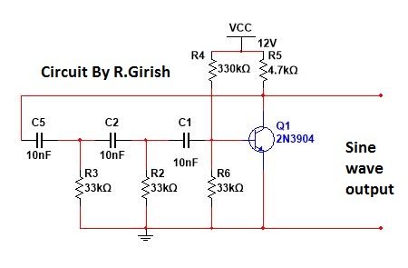

The complete circuit of a simple phase shift oscillator using just a single transistor is given above with explained 3 main parts.
The frequency can be determined by following formula:
Frequency = 1 / 2 x pi x R x C x sq. Root (2N)
Where R is the resistor in Ohms
C is the capacitance in Farads
N is the number of RC stage, N=3
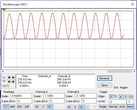
Here is the simulated output: