

This explained simple emergency lamp circuit includes a built-in charger which charges a nickel-cadmium battery through the input AC mains in order to get a standby power for emergency lighting in case of a mains outage.
How it Works

As soon as the 220V or 120 V mains supply fails, the connected lamps are turned on instantly. The design of the unit is quite straightforward.
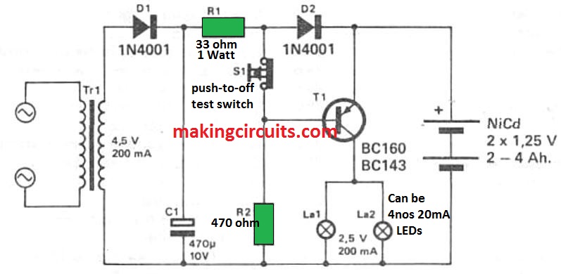
Tr1, D1 and C1 supply a halfwave rectified and filtered DC supply of around. 6 V, employed to consistently charge the NiCad battery at approximately 100 mA by means of R1 and D2.
A 2 Ah NiCad battery may be charged correctly at this specified rate. The voltage drop around D2 reverse-biases the base-emitter junction of T1, to ensure that this transistor is switched off and the bulbs aren't illuminated.
Once the mains AC input fails, at the same instant, T1 is provided with base current through R2; the transistor as a result activates and the lights are switched ON.
When the mains supply comes back, T1 quickly switches off, and the lamps are shut off enabling the battery to once again get charged via R1 and D2.
The proposed simple emergency lamp circuit could be installed anywhere an emergency lighting may be necessary in case of a power malfunction.
Application
A distinct illustration is in that notorious black cupboard (meter box area) below the stairways, making sure that, whenever a fuse blows off, a replacing could be quickly implemented and fixed.
A transformer having a somewhat larger secondary voltage can be utilised, on condition that R1 is suitably rated to restrict the current by means of this resistor to aroumd 100 mA.