The write-up describes an easy circuit widely available for charging a minimum of 25 nos of Li-Ion cells collectively instantly, from a single voltage source or a 12V battery.
The Design
With regards to charging, Li-ion cells need a lot more strict guidelines when compared to lead acid batteries. This turns into particularly essential simply because Li-ion cells are likely to produce significant amount of heat during the course of the charging procedure, and if this heat generation turns out beyond control can easily lead severe harm to the cell or even a likely explosion.
In spite of this one positive thing regarding Li-ion cells is the fact they could be charged at full 1C rate initially, in contrast to lead acid batteries which does not permit a lot more than C/5 charging rate.
The above benefit permite Li-ion cells to get incurred at 10 times quicker rate than the lead acid counter part.
As mentioned above, since heat administration evolves into the significant issue, if this parameter is properly managed, the rest of the things turn out to be fairly easy. This means we are able to charge the Li-ion cells at full 1C rate without having to be worried relating to anything at all provided that we certainly have an issue that displays the heat generation from these cells and is linked to the needed corrective activities.
We have attempted to apply this by affixing a different heat sensing circuit which detects the heat from the cells and controls the charging current in case the heat begins deviating from safe levels.
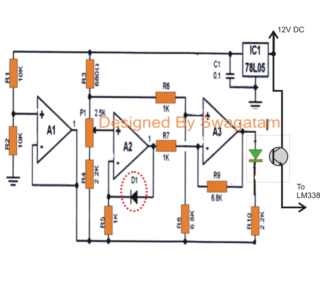
The first circuit diagram below demonstrates an accurate temperature sensor circuit utilizing the IC LM324. Three of its opamps have been utilized here.
The diode D1 is a iN4148 which efficiently works like the temperature sensor here. The voltage across this diode falls by 2mV with every degree rise in temperature.
This change in the voltage across D1 encourages A2 to change its output logic, which often is linked to A3 to slowly boost its output voltage in the same way.
The output of A3 is linked to an opto coupler LED. As per the setting of P1, A4 output has a tendency to rise in reaction to the heat from the cell, until finally the attached LED illuminates and the internal transistor of the opto performs.
At this point the opto transistor provides the 12V to the LM338 circuit for beginning the required corrective methods.
The second circuit demonstrates a basic controlled power supply making use of the IC LM338. The 2k2 pot is modified to generate precisely 4.5V across the associated Li-ion cells.
The preceding IC741 circuit is an over charge cut off circuit which manages the charge over the cells and disconnects the supply when it grows to above 4.2V.
The BC547 at the left near the ICLM338 is launched for making use of the suitable corrective steps when the cells start acquiring hot.
Just in case the cells commence acquiring too hot, the supply from the temperature sensor opto coupler hits the LM338 transistor (BC547), the transistor carries out, and immediately shuts off the LM338 output until the temperature comes down to regular levels, this method goes on until the cells get completely charged when the IC 741 triggers and disconnects the cells completely from the source.
In all 25 cells might be attached to this circuit in parallel, each positive line must include additional diode and a 5 Ohm 1 watt resistor for equal distribution of charge.
The whole cell package ought to be fixed over a common aluminum platform so that the heat is dissipated over the aluminum plate uniformly.
D1 needs to be pasted correctly over this aluminum plate so that the dissipated heat is optimally felt by the sensor D1.
Circuit for managing Li-ion battery charging heat
