In this post we study the method of making 3 simple constant current battery charger circuits, first one merely utilizes a single resistor, the second design incorporates a single Darlington BJT, while the 3rd circuit employs the IC LM317 for implementing the proposed current controlled charging of the connected batteries
A straightforward way of charging any battery originating from a higher voltage battery is demonstrated in the circuit below.
Suppose 4 large batteries needs to be recharged at 500 mA rate from a 12 volt battery, the resistor necessary could well be 12 - (4 x 1.25)/0.3 = 23.3 ohms, or perhaps a twenty two ohms will be more appropriate.
Just a single resistor is necessary to establish the specified charging current which is determined simply by dividing the difference in battery voltages from the current required for charging.

The wattage rating for your resistor can be determined through the square of the current multiplied by the resistance or (0.3)² x 22 = 2 watts, but a five watt or higher value is actually highly recommended.
The next circuit below demonstrates a constant current source accustomed to charge a team of 1 to 10 ni-cad batteries.
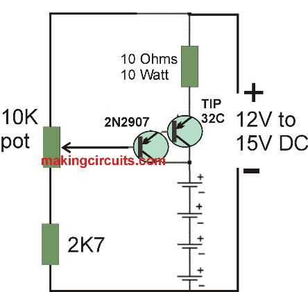
The emitter voltage of the TIP32 will probably be around one and half volts over the voltage on the slider of the pot. In the totally way up situation of the pot the transistors is going to be switched off and also the current is going to be in close proximity to 0V.
A pot is applied to establish the voltage in the emitter of the TIP32 that ensures the current over the output and the ten ohm resistor.
The TIP 32 transistor will likely waste around 7 watts when the output is overloaded and demands to be installed on a big heat sink.
This generates around 7 watts of temperature with a load using the maximum current through the 10 ohm resistor, therefore a ten watt or higher wattage may be necessary.
In case greater than 4 cells are hooked up, the utmost current obtainable may cut down and restricts the current adjustment to around A HUNDRED milliamps for TEN cells. The typical rate of charge with regard to high capacity (4AH) 'D' cells will be THREE HUNDRED to FOUR HUNDRED milliamps for 13 hrs and ONE HUNDRED milliamps intended for (1.2AH) 'C' or 'D' cells. With regard to smaller Nine volt battery packs the rate of charge can be Seven milliamps therefore you might slow up the range to 0-20 mA simply by using a 750 ohm resistor instead of the TEN. The charge current could be fixed by hooking up a ammeter along the output (ensuring that all the batteries are detached) after which fine-tuning the pot towards the ideal current, or through tracking the voltage throughout the TEN ohm resistor (1 volt = ONE HUNDRED mA) or (One volt = 1.33 mA having a 750 ohm resistor).
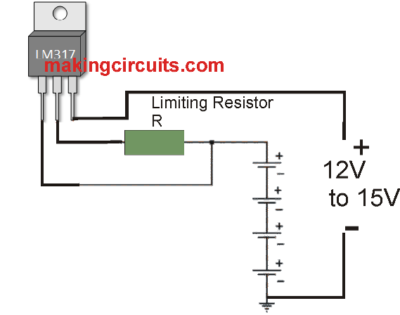
The simple constant current charger circuit above shows how to use a LM317 adjustable voltage regulator as a constant current source. The voltage in the middle of the wiper port and the end terminal is actually 1.25 volts, therefore simply by joining the wiper terminal with the load and inserting a resistor (R) somewhere between the load and the end terminal, a constant current of 1.25/R can be set up.
As a result you may require a TWELVE ohm resistor (R) for getting 100mA charging current and also a 1.2 ohm, 2 watt resistor with regard to One amp current. A diode can be used in series with the input in order to avoid the battery packs from implementing a opposite voltage towards the regulator IC in the event the power is switched off whereas the battery pack continue to be attached.
It's almost certainly recommended that you eliminate the battery packs ahead of switching off the supply voltage.
Ty Thompson says
Why was amperage dropped in the first example from 0.5a to 0.3 for the calculations?