• Skip to main content
  • Skip to primary sidebar

Making Easy Circuits

Learn and build electronic circuits

You are here: Home / Transmitters / Simple Wireless Headphone Circuit

Simple Wireless Headphone Circuit

Last Updated on January 10, 2018 by Admin Leave a Comment

 When somebody thinks about a simple wireless headphone circuit there are a few options that are generally visualized. The simplest of these options is incorporating IR or infrared light through which the audio signal to be transmitted is modulated and processed accordingly, while on the receiver side the signal is again demodulated and amplified appropriately for the achieving a successful wireless audio transfer.

wireless

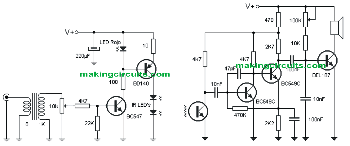
As shown in the image of the proposed simple wireless headphone circuit, the transmitter section looks extremely easy to build. The input small step-up transformer is wired as an impedance matching adapter, it has a low impedance winding which may be seen joined in parallel with the speaker of the TV or radio or whichever audio source that needs to be transmitted wirelessly.

The output from the transformer is further amplified by the two transistors and finally fed to a couple of series connected IR diodes

These infrared diodes are standard types and in fact any typical can be applied. We can also see a 10 ohm series resistor for controlling the current through the IR diodes and this resistor must be rated at 1w. This transmitter circuit works with a 9V supply which may be acquired from the audio source's power supply or through a separate 9V DC to DC adapter

The receiver for the wireless headphone circuit works in the following manner:

The detected IR or the infrared modulated beam from the phototransistor, is first preamplified and then amplified by the BC549C transistors, which is subsequently reinforced with extra power for enabling headphone speaker to operate and reproduce the received sound data.

This receiver too identically, like the transmitter operates using a 9V supply, however since the headphone needs to be wireless and the person able to walk with it, the supply needs to come from a battery. For this a few AAA cells wired up in series can be used to achieve the required 9V for the wireless headphone.

Remember that for the audio which is being transmitted ought to be within visual straight line between the transmitter and the receiver circuits because here we are dealing with IR concept and not an RF concept. Therefore if the two counterparts Tx, Rx are not within the line, noise may be introduced into the receiver causing distortion into the sound output.

In case you may feel that the range needs to be upgraded, It may be possible by increasing the range of the transmitter by enhancing the number of transistors for BD140 and/or by including more numbers of IR diodes in the series.

You'll also like:

  • 1.  Simple Stereo FM Transmitter Circuit
  • 2.  Walkie Talkie Circuit – Long Range
  • 3.  2 Small FM Transmitter Circuits Explained
  • 4.  Small Tracking Transmitter Circuit
  • 5.  Powerful Transceiver Circuit using IC MC2833/MC3363
  • 6.  1 Watt AM/CW Transmitter Circuit

About Admin

Hey friends, Thanks a bunch for stopping by this site! I am an engineer with a Bachelor of Engineering in Electronics and Telecommunication. One of my passions is gathering information from all sorts of electronics books and tutorials. I then take that information and compile it into a language that is super easy to understand. My goal is to make those complex electronics circuit concepts and technical terms much more accessible for all the new and budding electronics engineers out there. I can also design customized circuit diagrams as required by the users.
If you have any questions related to this field, please do not hesitate to drop a comment! I am always here and ready to help you out with any queries you might have. I cannot wait to hear from you!

Reader Interactions

Leave a Reply Cancel reply

Your email address will not be published. Required fields are marked *

Primary Sidebar

Categories

  • 3 Phase (4)
  • 8051 Microcontroller (1)
  • Arduino (11)
  • Audio and Amplifier (102)
  • Automation (8)
  • Battery Chargers (64)
  • Bicycle Projects (4)
  • Car and Motorcycle Projects (39)
  • Datasheets (10)
  • DIY Projects (5)
  • Electrical (15)
  • Free Energy (6)
  • Games Projects (2)
  • High Voltage (14)
  • Hobby Projects (30)
  • Household Circuits (2)
  • IC 555 Circuits (4)
  • Ignition Circuits (2)
  • Indicators (50)
  • Infrared (6)
  • Inverter Circuits (29)
  • Lights and Lamps (97)
  • Medical (8)
  • Meter and Tester Circuits (38)
  • Motor Driver (17)
  • New Circuits (56)
  • Oscillators (30)
  • Pets and Pests (5)
  • Power supply (81)
  • Protection Circuits (25)
  • PWM (8)
  • Remote Control (20)
  • Security and Alarm Circuit (48)
  • Sensors and Detectors (66)
  • Signal Processor (23)
  • Solar Controller Circuits (61)
  • SSR (3)
  • Temperature Controller (20)
  • Timer (25)
  • Transformerless (7)
  • Transmitters (12)
  • Tutorials (45)
  • UPS (2)
  • Voltage Regulators (57)
  • Water Sensor and Controller (29)
  • Home
  • Privacy Policy
  • Contact
  • Disclaimer
  • Copyright

© 2025 · Making Easy Circuits