Ok, now this first circuit which we made using transistor is simple right, but there is one problem which is, it may not work very accurately. Meaning ok, so now what happens the relay, it might not switch ON and OFF at the exact same time every day, like at dawn or dusk, it can be slightly different each time.
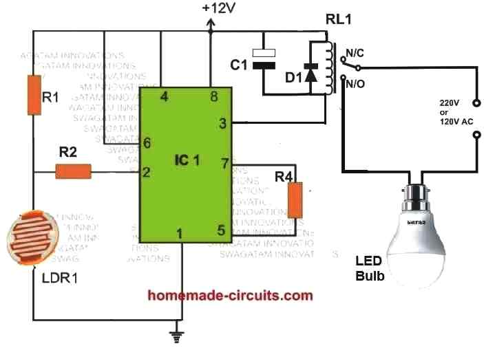
So now we move on here, and we see there is another better design below, where we use IC 555 and this one solves the above problem very effectively, ok. So why, because inside this IC 555 there is an op amp which controls the switching, making sure the relay always changes state at the same light level, every single day, throughout the year, ok. This means the street light will switch ON and OFF at almost the exact same time every evening and morning, right.
Parts List
| Component | Value/Specification |
|---|---|
| R1 | 220K 1/4 watt resistor or 1M preset |
| R2 | 1M 1/4 watt resistor |
| R3 | 10K 1/4 watt resistor |
| R4 | 100K 1/4 watt resistor |
| LDR1 | Any standard LDR |
| C1 | 220uF electrolytic capacitor |
| D1 | 1N4007 Diode |
| T1 | BC547 Transistor |
| IC1 | 555 IC |
| RL1 | 12V relay, 200 to 400 ohm coil resistance |
| LED Bulb | Any 100W LED bulb or as per street light requirement |
| 12V SMPS | 1 unit for powering the circuit |
Now here in this circuit, IC 555 is not working in its usual way right, we are not making it work as a timer, instead we are just using it as a simple comparator, ok.
Now we can set at what light level the switching must happen, using this part R1. We can keep R1 as a fixed 220K resistor if we do not want much adjustment but if we want precise setting then we can use a 1M preset here instead, ok.
How it Works
Now let us see how this works, ok.
During daytime, when there is a lot of sunlight falling on the LDR what happens the LDR resistance goes low, right. Now due to this, the pin#2 of the IC gets connected to ground, so its voltage stays low. This makes the IC's pin#3 voltage go high.
Since the relay is connected to pin#3, it remains OFF. Now because the relay is OFF, its contacts stay at the N/C position. But now, the lamp is connected at the N/O position, so if relay is OFF, lamp will also remain OFF.
Now as night starts to come, what happens, the light on the LDR starts decreasing. As a result now its resistance increases. Due to this, a positive voltage develops at pin#2 of the IC via R1. So when this happens then the IC's pin#3 now becomes low which means now it switches ON the relay.
Now when the relay is switched ON then its contacts shift from N/C to N/O position. But now we see, lamp is at N/O, so when relay changes position then now lamp turns ON, right.
So this is how every evening when it gets dark, then relay switches ON and the lamp lights up and every morning when it gets bright, then relay switches OFF and the lamp shuts down, ok.
Now here one thing we must understand that the IC 555 in this circuit is not used as an astable or monostable circuit but just as a simple comparator. Normally IC 555 works like this: When its pin#2 gets a low signal then its output at pin#3 goes high.
This low signal is when voltage at pin#2 is below one-third of the supply voltage. But when voltage at pin#6 goes above two-thirds of supply voltage, then the output at pin#3 goes low again, ok.
In this circuit pin#6 is not actually used, it is directly connected to positive supply, so output only depends on pin#2 voltage, ok.
Now if we want to control how sensitive this circuit is then we can connect a resistor between pin#5 and pin#7 of the IC, like shown in diagram. This resistor sets the hysteresis level. If we use a lower value resistor then hysteresis will be higher, if we use a higher value resistor then hysteresis will be lower.
A 100K resistor is a good starting value but we can experiment by using a potentiometer here also.
Now one important thing, the power supply voltage for this circuit must be same as the relay coil voltage. But do not go above 16V, because IC 555 can get damaged. Best is to use 12V, because at 12V, this circuit will consume only 4mA current, without relay.
There is another thing, the components R2 and C1 they create a small delay of about 2 seconds before the relay switches ON. This delay helps prevent unnecessary relay switching due to sudden changes in light, like a car headlight flashing on the LDR.
How to Set Up
Now here is how we can set up this circuit properly, right.
First we replace R1 with a 1M preset, ok.
Then we turn its wiper fully towards the positive supply side.
Next we cover the LDR with something dark, so that no light falls on it.
After this, we illuminate the surrounding with exactly the amount of light at which we want the relay changeover to happen, right.
Now we switch ON the power and then we remove the cover from LDR.
After this, we slowly adjust the preset R1 until we see the lamp just turns OFF.
Now the circuit is set, ok.
So to test if it is working correctly, we cover the LDR with a finger and check what happens. If the circuit is correct then the relay should instantly activate, which means the lamp should turn ON. Then, when we remove the finger from LDR, then lamp should turn OFF again.
That is all, now circuit is fully ready and will work every day automatically, switching ON the lamp at night and switching it OFF in the morning, great, right?.
How do we Build it
Ok, now here we will see how to construct this IC 555 based automatic street light circuit, step by step, ok.
Step 1: Get all the Components Ready
First we must collect all the required components, ok. So here we need:
One IC 555,
One relay, 12V type,
One LDR,
Resistors R1, R2, and R4,
Capacitor C1,
One diode D1,
A LED bulb,
Some wires, PCB, soldering tools, and a 12V power supply.
Step 2: Mount the IC 555
Now we take the IC 555 and place it properly on a PCB. It is better if we use an IC base, so later if IC gets damaged, we can replace it easily, ok.
Step 3: Connect the Power Supply Pins
Now we take a wire and connect pin#8 of the IC to the +12V supply.
Then we connect pin#1 to ground.
Now the IC has power to work, ok.
Step 4: Connect the LDR and Resistors
Now we take the LDR and place it properly on the PCB.
One end of the LDR is connected to ground.
The other end is connected to pin#2 of the IC.
Then we connect R1 between pin#2 and +12V, ok.
Now, LDR and R1 will create a voltage divider, which will sense light and darkness.
Step 5: Add Hysteresis Resistor
Now we take R2 and connect it between pin#6 and pin#2.
This will create a small hysteresis effect, so the relay does not keep switching ON and OFF rapidly, ok.
Step 6: Connect the Relay Circuit
Now we take the relay and place it on the PCB.
One side of the relay coil is connected to +12V.
The other side of the relay coil is connected to pin#3 of the IC, through R4.
Now the relay will switch ON and OFF depending on the IC output.
Step 7: Add Protection Diode
Now we take diode D1 and connect it across the relay coil.
The cathode (white stripe side) goes to +12V and the anode goes to pin#3 side.
This will protect the IC from the back EMF of the relay, ok.
Step 8: Connect the Lamp Load
Now we take the LED bulb and connect it to the relay contacts.
One wire of the LED bulb goes to the AC supply.
The other wire goes to the relay N/O contact.
The common terminal of the relay is connected back to the AC supply.
Now when the relay switches ON then the LED bulb will turn ON, ok.
Step 9: Add the Delay Capacitor
Now we take capacitor C1 and connect it between pin#5 of the IC and ground.
This will create a small delay, so that the relay does not react too fast to sudden light changes.
Step 10: Testing and Adjustments
Now we power ON the circuit and check how it works, ok.
During daytime or bright light, the LDR resistance will be low, so pin#2 voltage will be low, making pin#3 output high, which means the relay will be OFF, and the lamp will remain OFF, ok.
During nighttime or darkness, the LDR resistance will be high, so pin#2 voltage will rise, making pin#3 output low, which means the relay will turn ON, and the lamp will light up, ok.
If we want to adjust the light level at which the lamp should turn ON then we can replace R1 with a preset and adjust it as needed.
Final Step: Fix Everything in Place
Once everything is working correctly, then we can solder all the connections properly, mount the LDR in a proper position where it can sense daylight properly and enclose the circuit in a waterproof box if used outdoors.
That is all, now this IC 555 automatic street light circuit is ready and it will switch ON and OFF automatically every day, based on the surrounding light, ok.
Leave a Reply