The post discusses a simple high intensity mains 220V powered xenon tube stroboscope circuit using minimum number of parts.
A xenon tube stroboscope is a high intensity light effect generator using a high voltage xenon gas discharge tube flashing.
How it Works
Preset P1 should include a nylon shaft to ensure that non-e of its metallic elements might be touched: ignoring this may be lethal.

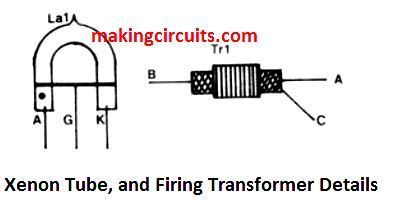
As shown in the figure above the main part of the device is, no doubt, the gas discharge tube, which usually is available in U-shaped tube and is manufactured with xenon inside (Xe – which is one of the inert gases). The tube is installed with an anode and cathode at two of its ends, and an ignition grid. Diodes D1 and D2, along with capacitors C1 and C2, constitute a voltage doubler that boosts the DC voltage to roughly 600 V.
This voltage is applied on the anode and cathode of the tube. Commonly, xenon and other inert gases acy like a bad conductor of electricity nevertheless the electric field as a result of the 600 V potential across the anode and cathode leads to ionization of molecules and atoms just around these electrodes.
The gaseous ions tend to be pulled towards the charged electrodes and a tiny preconducting current starts moving. A grid voltage of 5 … 10 kV becomes necessary to trigger and light up the tube, that implies the gas has to be broken down in order to allow a substantial current to move through the tube. The fairly excessive grid voltage is acquired from ignition transformer TR1.
In order to create a high voltage over the secondary, the current by way of the primary must be cut off very quickly and this is carried out through a silicon controlled rectifier, Th1. Capacitor C3 charges since the voltage around C2 is 500 V and the primary of Tr1 is low resistance.
The moment the limit of the a couple of triggering diodes, D3 and D9, is attained, the SCR is fired. Capacitor C3 then discharges vary quickly by means of the Tr1 primary winding which inflicts a extremely large voltage in the secondary and this subsequently leads to the xenon tube to spark and dazzle with high illumination.
The adjustment of preset P1 ascertains the C3 charging rate and as a result the triggering cycles of the xenon tube. Resistor R1 is attached within the neutral line to work like a current limiter, mainly because as soon as the xenon tube is in the firing mode it is a practical short-circuit; without having R1 the fuse F1 would immediately burn. The xenon tube, that ought to be of the 60 W/s type, is frequently supplied including ignition transformer. The anode is normally pointed out by a red dot.
WARNING! The stroboscope circuit explained below is linked directly to the AC mains and tests within the uncovered system is for that reason extremely hazardous. Even after the device is unplugged from the mains many capacitors might continue to have lethal charge stored in it giving a painful shock!
Leave a Reply