• Skip to main content
  • Skip to primary sidebar

Making Easy Circuits

Learn and build electronic circuits

You are here: Home / Audio and Amplifier / Amplifier/Loudspeaker Overload Protector Circuit

Amplifier/Loudspeaker Overload Protector Circuit

Last Updated on November 16, 2024 by Admin 3 Comments

At the time of dealing with high power amplifier designs, two things turn out to be essential, the security of the amplifier and the safety of the speakers from an accidental over current influx.

Particularly whenever the amplifier design entails expensive mosfets, the design turns into in particular susceptible to short circuits at the outputs.

A brief circuit at the output might be triggered as a result of mishandling or ignorance from the part of the user.

Anything could be the cause, the final result in the devastation of the valuable mosfets inside the amplifier box.

The above mishap may be eliminated by attaching a small circuit for detecting a brief circuit conditions at the outputs of an amplifier.

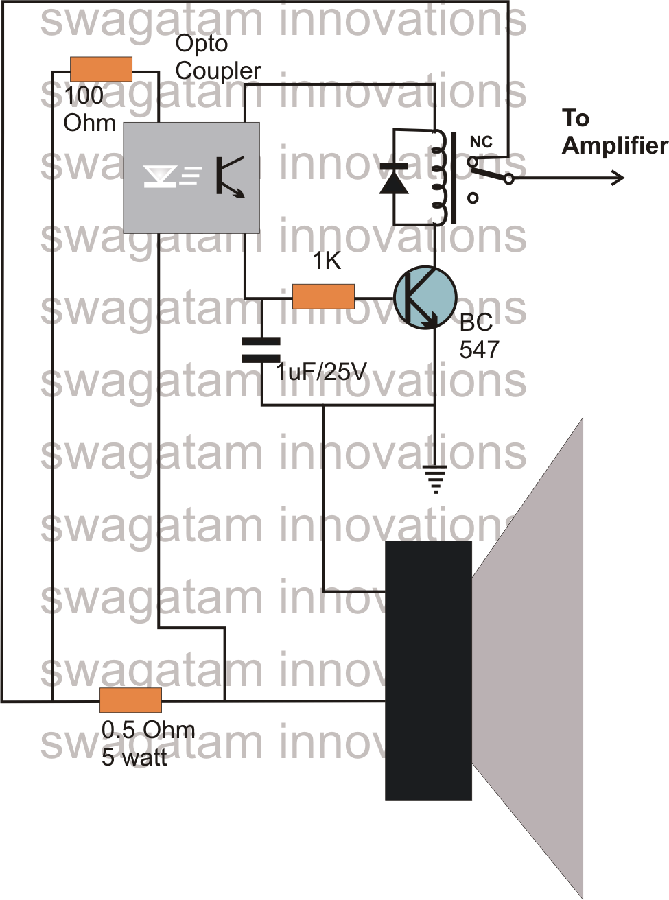
The presented amplifier short/overload protection circuit diagram, demonstrates a cheap design utilizing just a single transistor for applying the meant feature.

Usually a low value resistor is normally used at the output of mosfet amplifiers, the current designed across this resistor could be well used for tripping a relay just in case it surpasses the safe highest current value.

The current threshold across the above resistor is felt by an LED inside an optocoupler, which illuminates the instance a short or overload problems is imagined.

This immediately causes the opto transistor which often switches ON the transistor driver and the connected relay mechanism.

Considering that the relay coils assist the amplifier link to the speaker output, disconnects the amplifier from the output connection, stopping the amplifier devices from a likely harm.

The capacitor at the base of the transistor maintains the transistor switched for a few seconds so that the relay will not oscillate randomly.

Amplifier/Loudspeaker Overload Protector Circuit

You'll also like:

  • 1.  70 Watt High Efficiency Power Amplifier Circuit Using IC TDA1562
  • 2.  Digital Volume Controller Circuit
  • 3.  Simple Mains Overload Protection Circuit
  • 4.  Buzzer Circuit Using a Transistor and Piezo Element
  • 5.  Powerful Bass Booster Amplifier Circuit
  • 6.  Electronic Bongo Circuit

About Admin

Hey friends, Thanks a bunch for stopping by this site! I am an engineer with a Bachelor of Engineering in Electronics and Telecommunication. One of my passions is gathering information from all sorts of electronics books and tutorials. I then take that information and compile it into a language that is super easy to understand. My goal is to make those complex electronics circuit concepts and technical terms much more accessible for all the new and budding electronics engineers out there. I can also design customized circuit diagrams as required by the users.
If you have any questions related to this field, please do not hesitate to drop a comment! I am always here and ready to help you out with any queries you might have. I cannot wait to hear from you!

Reader Interactions

Comments

  1. Cidess says

    September 9, 2020 at 10:48 am

    Thanks Sir!

    Reply
  2. Cidess says

    September 8, 2020 at 4:04 pm

    Hello, Can you give me the formula to calculate the output resistor?
    Thanks.

    Reply
    • admin says

      September 9, 2020 at 8:52 am

      The indicated 0.5 ohm is calculated using the following formula:

      R = 1.5 / cut-off current

      Reply

Leave a Reply Cancel reply

Your email address will not be published. Required fields are marked *

Primary Sidebar

Categories

  • 3 Phase (4)
  • 8051 Microcontroller (1)
  • Arduino (11)
  • Audio and Amplifier (102)
  • Automation (8)
  • Battery Chargers (64)
  • Bicycle Projects (4)
  • Car and Motorcycle Projects (39)
  • Datasheets (10)
  • DIY Projects (5)
  • Electrical (15)
  • Free Energy (6)
  • Games Projects (2)
  • High Voltage (14)
  • Hobby Projects (30)
  • Household Circuits (2)
  • IC 555 Circuits (5)
  • Ignition Circuits (2)
  • Indicators (50)
  • Infrared (6)
  • Inverter Circuits (29)
  • Lights and Lamps (97)
  • Medical (8)
  • Meter and Tester Circuits (38)
  • Motor Driver (17)
  • New Circuits (56)
  • Oscillators (30)
  • Pets and Pests (5)
  • Power supply (80)
  • Protection Circuits (25)
  • PWM (9)
  • Remote Control (20)
  • Security and Alarm Circuit (48)
  • Sensors and Detectors (66)
  • Signal Processor (23)
  • Solar Controller Circuits (62)
  • SSR (3)
  • Temperature Controller (20)
  • Timer (25)
  • Transformerless (7)
  • Transmitters (12)
  • Tutorials (45)
  • UPS (2)
  • Voltage Regulators (57)
  • Water Sensor and Controller (29)
  • Home
  • Privacy Policy
  • Contact
  • Disclaimer
  • Copyright

© 2025 · Making Easy Circuits