In this article we are going to take a closer look at the fundamental idea behind a solar inverter and we will also explore how to create a small or mini but effective solar inverter circuits.
Solar energy is something that is abundantly available to us and it does not cost anything to use in addition it is an endless and natural source of energy that is easily accessible for everyone.
The Importance of Solar Inverters
Now let us talk about solar inverters. To be honest there is nothing particularly crucial about solar inverters. You can simply take any regular inverter circuit connect it to a solar panel and you will obtain the necessary DC to AC output from that inverter.
That being said it is important for you to choose and configure the specifications correctly because if you do not you might end up damaging your inverter or causing inefficient power conversion which is something we definitely want to avoid.
Why Do We Need a Solar Inverter
We have already mentioned how we can utilize solar panels to generate electricity from the power of the sun and in this article we are going to discuss a simple setup that will allow us to harness solar energy for running our household appliances.
A solar panel has the ability to convert sunlight into direct current at lower voltage levels. For instance a solar panel might be rated to provide 36 volts at 8 amps when conditions are optimal.
However we cannot directly use this level of power for powering our home appliances because these appliances are designed to operate only at mains voltage which typically ranges from 120 volts to 230 volts.
Furthermore the current that we require needs to be alternating current or AC rather than direct current or DC which is what we usually get from a solar panel.
We have encountered various inverter circuits discussed in this blog and we have learned about their functioning.
Inverters serve the purpose of converting and stepping up low voltage battery power into high voltage AC mains levels.
As a result inverters can be effectively utilized for transforming the DC output from a solar panel into mains outputs that can suitably power our domestic equipment.
Essentially inverters make it possible for us to convert from a low potential level to a higher mains level due to the high current that is typically available from DC inputs such as batteries or solar panels while keeping the overall wattage consistent.
Understanding Voltage and Current Specifications
To illustrate let us consider an example where we supply an input of 36 volts at 8 amps to an inverter and receive an output of 220 volts at 1.2 amps. This means that we have transformed an input power of 36 multiplied by 8 which equals 288 watts into an output power of 220 multiplied by 1.2 which equals 264 watts.
Thus we can see that there is no magic involved here it is simply a matter of adjusting the respective parameters.
If the solar panel generates sufficient current and voltage its output can be used directly to operate an inverter along with the connected household appliances while also charging a battery at the same time.
The charged battery can then be utilized for powering loads through the inverter during nighttime when solar energy is not available.
However if the solar panel is smaller in size and does not generate enough power it may only be used for charging the battery which then becomes useful for running the inverter after sunset.
Circuit Operation Explained
Now let us take a look at the circuit diagram where we can see a simple setup involving a solar panel an inverter and a battery.
These three components are connected through a solar regulator circuit that manages the distribution of power among them after appropriately regulating the power received from the solar panel.
Let us assume that the voltage provided by the solar panel is 36 volts and the current is 10 amps. In this case we would select an inverter with an input operating voltage of 24 volts at 6 amps giving us a total power output of approximately 120 watts.
A portion of the current from the solar panel which amounts to around 3 amps is reserved for charging a battery that will be used after sunset.
We also assume that our solar panel is mounted on a solar tracker so it can deliver its specified requirements as long as sunlight is available in the sky.
The input power of 36 volts goes into the regulator which reduces it down to 24 volts.
The load connected to the output of the inverter has been chosen so that it does not require more than 6 amps from the solar panel.
From the remaining current of 4 amps two amps are directed towards charging the battery while the other two amps are left unused in order to maintain better efficiency throughout the entire system.
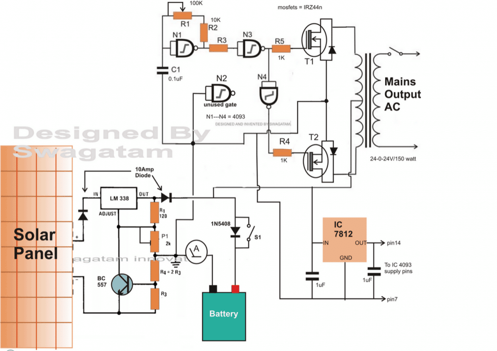
Parts List for the LM338 charger section
| Component | Specifications |
|---|---|
| Resistors | All resistors are 1/4 watt, 5% CFR unless specified |
| R1 | 120 Ohms |
| P1 | 10K Pot (2K is mistakenly shown) |
| R4 | Replace with a link |
| R3 | 0.6 x 10 / Battery AH |
| Transistor | BC547 (not BC557, it is mistakenly shown) |
| Regulator IC | LM338 |
Parts List for the Inverter Section
| Component | Specifications |
|---|---|
| Resistors | All parts are 1/4 watt unless specified |
| R1 | 100K Pot |
| R2 | 10K |
| R3 | 100K |
| R4, R5 | 1K |
| T1, T2 | MOSFET IRF540 |
| N1 - N4 | IC 4093 |
Parts That Do Not Require Specification
There are a few remaining parts in the circuit that do not need to be specified in detail and can simply be copied as they are shown in the diagram.
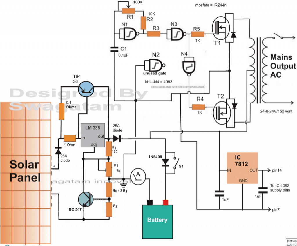
Charging Batteries with Capacities Up to 250 Ah
When it comes to the charger section in the circuit I mentioned earlier it can be upgraded in a suitable manner to allow for the charging of high current batteries that fall within the range of 100 Ah to 250 Ah.
If you are working with a 100 Ah battery you can easily replace the LM338 component with an LM196 which is a version of the LM338 that can handle up to 10 amps.
To facilitate the necessary high current charging an outboard transistor known as TIP36 is appropriately integrated across the IC 338.
It is important to calculate the emitter resistor for the TIP36 carefully because if you do not it is possible that the transistor could blow out.
To determine the right value for this resistor you can use a trial and error method.
I suggest starting with an initial value of 1 ohm and then gradually reducing it until you reach the required amount of current at the output.
Incorporating a PWM Feature
In order to ensure that I have a stable output of either 220 volts or 120 volts I can add a PWM control feature to the designs I mentioned earlier as illustrated in the diagram that follows.
As you can observe the gate N1 which is essentially set up as an oscillator operating at either 50 Hz or 60 Hz is improved by integrating diodes along with a potentiometer. This enhancement allows for the option of having a variable duty cycle which provides greater flexibility in controlling the output.
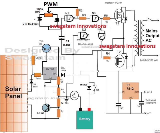
Adjusting the Potentiometer
When we make adjustments to this potentiometer we have the ability to compel the oscillator to generate frequencies that have varying ON and OFF periods. This adjustment will consequently enable the MOSFETs to turn ON and OFF at the same rate which is quite important for our purposes.
Varying Current Induction
By modifying the timing of the MOSFETs turning ON and OFF we can proportionately change the amount of current that is induced in the transformer. This change will ultimately give us the capability to adjust the output RMS voltage of the inverter as needed.
Fixing Output RMS Voltage
Once we have established a fixed output RMS voltage the inverter will then be capable of producing a steady output regardless of any variations in solar voltage. However it is important to note that this will continue only until the voltage drops below the specifications set for the primary winding of the transformer.
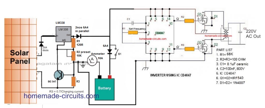
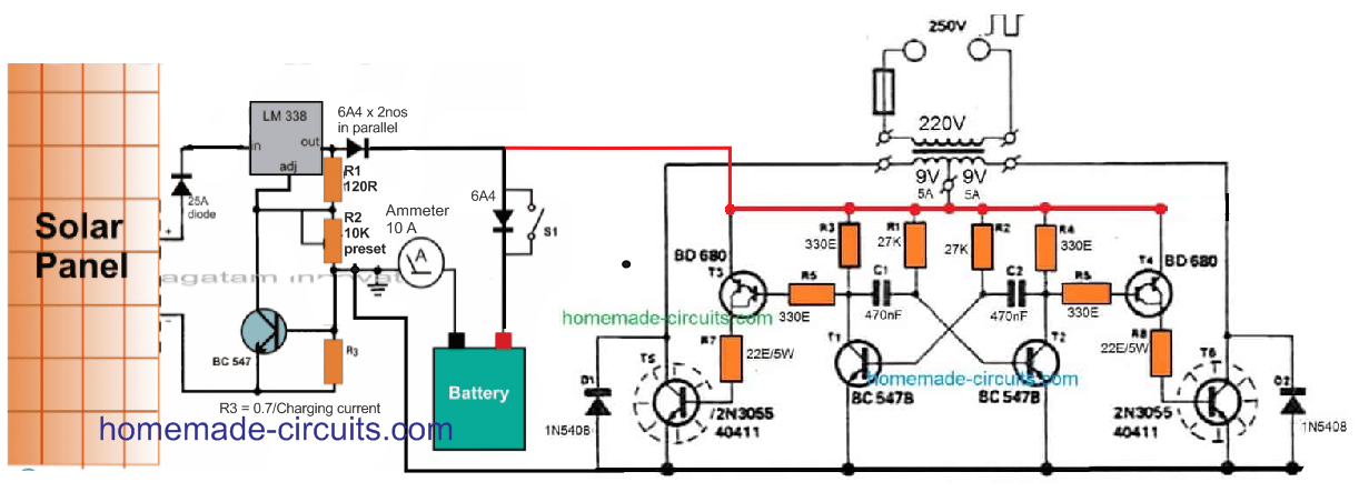
Solar Inverter Utilizing IC 4047
As I mentioned earlier it is possible for you to connect any inverter that you desire with a solar regulator in order to easily implement a solar inverter function.
The diagram that follows illustrates how a straightforward IC 4047 inverter can be utilized alongside the same solar regulator to obtain either 220 V AC or 120 V AC from your solar panel setup.
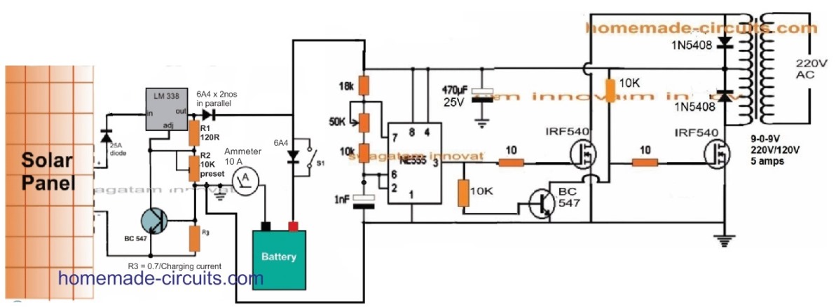
A solar inverter that uses an IC 555
Likewise to this, we can definitely use an IC 555 inverter to make a tiny solar inverter by combining it with a solar panel to obtain the necessary 220V AC.
Solar Inverter with Transistor 2N3055
Each one electronic aficionados have a strong preference for the 2N3055 transistors. Additionally, you can construct rather strong inverters having a minimal amount of parts thanks to this incredible BJT.
The following straightforward design will help you realize your ambition if you're one of those people who has a couple of these gadgets in your trash box and would want to use them to make a fantastic tiny solar inverter.
A basic solar inverter without a controller for charging
For customers who are not too interested in incorporating the LM338 charger controller, the next PV inverter design appears to be a viable choice for cost-effectiveness.
If the solar panel receives the necessary quantity of direct sunlight, the battery will still charge properly regardless of whether it could be viewed without a regulator.
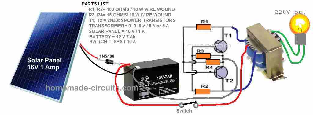
The design's minimalism also suggests particularly lead acid batteries really are not that hard to charge.
Keep in mind that it can take at least 8 to 10 hours to charge completely a totally drained battery (roughly 11V) before the inverter is capable of being turned on for the necessary 12V to 220V AC conversion.
Easy Switch from Solar to AC Main
One may add an additional relay adjustment to the LM338/LM196 regulator input if you would like your solar inverter system to get the ability to switch automatically from solar panels to mains grid AC:
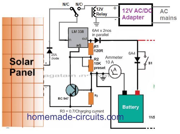
When it comes to using a 12V adapter it is really important that this adapter is rated appropriately to match the voltage of the battery as well as its amp hour specifications.
For instance if you have a battery that is rated at 12 volts and has a capacity of 50 amp hours then you can use a 12V adapter that has a voltage rating anywhere between 15 volts to 20 volts along with a current rating of 5 amps.
Exploring Solar Inverters with Buck Converters
In the previous discussion we took a closer look at how to create a straightforward solar inverter that also functions as a battery charger by utilizing linear integrated circuits such as the LM338 and the LM196. These components are particularly useful when the voltage and current produced by the solar panel align perfectly with what the inverter requires.
In situations like these the wattage capacity of the inverter tends to be relatively small and limited. However when dealing with inverter loads that demand significantly higher wattage it becomes necessary for the output power from the solar panel to also be substantial enough to meet those requirements.
In this particular context it is essential for the solar panel to generate a much higher current. The challenge arises because while there are solar panels available that produce high current at low voltage creating high wattage solar inverters ranging from around 200 watts to one kilovolt appears to be quite difficult.
On the other hand high voltage and low current solar panels are readily available in the market. Since we know that wattage can be calculated using the formula W equals V multiplied by I it follows that solar panels with higher voltages can easily facilitate a greater wattage output.
That being said it is crucial to note that these high voltage solar panels cannot be utilized in applications involving low voltage and high wattage inverters because there may be compatibility issues regarding voltage and current.
For example let us consider a scenario where we have a solar panel rated at 60 volts and producing 5 amps alongside a 12 volt inverter with a capacity of 300 watts. Even though the wattage ratings of both components might seem similar they cannot be connected together due to their differing voltage and current specifications.
This is precisely where a buck converter proves to be extremely useful as it can effectively convert any excess voltage from the solar panel into additional current while also reducing any excess voltage in accordance with what the inverter requires.
Leave a Reply